
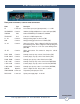
Specifications


e-mail:
support@broadcasttools.com
voice:
360.854.9559
fax:
866.783.1742
10
WVRC-4 Installation and Operation Manual
INSTALLATION
TEMP Sensor Probe Input
Insert the temperature probes (25 foot cable) mini (3.5mm) plug in to the rear panel
jack labeled “TEMP” (-40°F to +190°F (-40°C to +85°C).
NOTE: Please limit the total length of cable to 50 feet. Please contact the fac-
tory for the proper extension cable. The temperature probe should only be
installed or removed with the power supply disconnected from the WVRC-4.
POTS Telephone Line RJ11
Connect one end of the supplied RJ11 modular cable to the rear panel RJ11 jack
labeled “LINE” and the other end to the telephone line.
NOTE: Some “cell phone services” severely distort DTMF control tones
resulting in unreliable control. If you plan on using the cellular system for your
POTS connection, you may have to experiment with various service providers
to get reliable control. With some cellular phone services, you may need to
change the DTMF guard time jumper to the “FAST” position. We recommend
using a product from Telular “Phonecell® SX5D or SX7” which is designed for
the GSM system (www.telular.com/).
PGM, RJ11, TT phone
Connect the modular cord of the user supplied TT telephone to the front panel RJ11
jack labeled “PGM”
PGM, RS-232 female DB-9 connector
Connect one end of the supplied male/female straight-thru serial cable to this con-
nector and the female end to a user provided PC (this may not be needed if the user
elects to program the dial-up portion via telnet (INTERNET).
NETWORK connector
Connect one end of the supplied CAT5 (straight or xover) cable to desired ETHER-
NET port.
POWER connector (12VAC)
Connect the supplied 12VAC power supply cord in to the WVRC-4’s power jack
labeled “12 VAC @ 1 amp”, then plug the transformer in to a source of 120vac
60Hz. Verify that the front panel green power led is illuminated.
WEBSITE:
Visit our web site for
product updates and
additional information.