
Specifications


e-mail:
support@broadcasttools.com
voice:
360.854.9559
fax:
866.783.1742
7
WVRC-4 Installation and Operation Manual
INSTALLATION
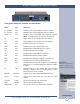
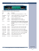
Rear panel indicators, controls and connectors
Name Type Description
PF 2.1mm Jack Power Failure power jack (optically-isolated). 6 - 12 VDC.
SSL/GND/SSR Connector Unbalanced left/ground/right silence sensor audio input (BOT)
LAN/WAN RJ45 Network ETHERNET port 10/100baseT, LAN/WAN
TELCO LINE RJ11 Connects to a POTS telephone line
A1 - A4 Connector Analog (metering) inputs one thru four (TOP)
GND Connector Analog (metering) ground reference terminals (TOP)
1A - 4A Connector Status opto-isolators. When configured for DRY (factory default)
this terminal is ground. When configured for WET (floating), this
terminal is the Anode via a 2.2K ohm current limiting resistor.
(BOTTOM)
1B - 4B Connector Status opto-isolators. This terminal is always the cathode
(BOTTOM)
R1NC - R4NC Connector Normally closed, dry relay contacts. Raise function (TOP)
R1CM - R4CM Connector Common (wiper), dry relay contact. Raise function (TOP)
R1NO - R4NO Connector Normally open, dry relay contact. Raise function (TOP)
L1NC - L4NC Connector Normally closed, dry relay contact. Lower function (BOTTOM)
L1CM - L4CM Connector Common (wiper), dry relay contact. Lower function (BOTTOM)
L1NO - L4NO Connector Normally open, dry relay contact. Lower function (BOTTOM)
CONFIG Dipswitch Used to configure the unit. Refer to table of contents.
TEMP SENSOR 3.5mm Jack Temperature probe input jack. T/R/S.
PWR/12VAC 2.1mm Jack System power supply input. 12 volts AC