
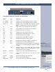
Specifications


e-mail:
support@broadcasttools.com
voice:
360.854.9559
fax:
866.783.1742
9
WVRC-4 Installation and Operation Manual
INSTALLATION
Status Inputs
Each of the four optically isolated status inputs can be configured to accept either a
contact closure (dry = default) or a (floating, wet). Attach your dry contacts to the
desired status channels StxA and STxB (where x is the status input) terminals.
Each input is equipped with a four-position header. Each input is labeled IN-x
(where x is the status input) and the header pins are labeled 1,2,3,4. The factory
default is a DRY input (switch, relay contact) with jumpers between 1 & 2 and 3 &
4. In the dry configuration, the “A” terminal is ground while the “B” terminal is the
cathode of the opto diode (pulled up to 5 volts through a 2.2K resistor).
To change the status input to (floating) WET (user supplied voltage between 5 and
24vdc), remove both jumpers and place ONE jumper over pins 2 & 3. Connect the
positive voltage to terminal “A” (anode) and ground or minus voltage to terminal
“B”(cathode). ! NOTE: Please observe proper polarity.
Raise/Lower Relays
Raise and lower relays K1 through K4 are supplied with SPDT dry contacts.
Equipment to be controlled by the RAISE relays should be connected to the TOP ter-
minals labeled RxNC, RxCM and RxNO (where x is the channel number), while
equipment to be controlled by the LOWER relays should be connected to the BOT-
TOM terminals labeled LxNC, LxCM and LxNO (where x is the channel number).
NOTE: If mechanical latching relays are required, we suggest the Broadcast
Tools LR-5 (4PDT & 1SPST) mechanical latching relay.
Power Failure Input
Connect a user supplied 6 to 12 volts DC only power source (center positive) to the
power failure input labeled PF. The barrel connector size is 2.1mm ID x 5.5mm OD.
An inexpensive 6 to 12 volts DC wall transformer of any current of 50 ma or more
will work.
NOTE: The primary (120vac) of the wall transformer should be connected to
the utility company side of your service. An UPS is suggested to power the
WVRC-4 during power outages.
Silence Sensor Inputs
Connect your unbalanced monaural or stereo audio source to the terminals labeled
SSL, GND and SSR. The level should be between –10 and +8 dbu. The input
impedance is approximately 10K ohms. When the SS is activated, you can adjust
the SS Sense trimmer for an illuminated front panel SS led. If the SS led is out, the
signal is low and if it’s flashing, it in an alarm condition (if enabled). The silence
sensor signal can only be aurally monitored in dial-up mode. The front panel SS
Mon trimmer should be adjusted for a comfortable level at the caller end.
CAUTION! If the SS MON level is too high, the unit may have trouble detecting
DTMF tones. NOTE: The DTMF guard time jumper is factory set to the “MED”
position for enhanced tone detection. In some applications, your may need to move
this jumper.