
Specifications


ee--mmaaiill::
support@broadcasttools.com
vvooiiccee::
360.854.9559
ffaaxx::
866.783.1742
7
SRC-8 III Installation and Operation Manual
INSTALLATION
Connecting Multiple SRC-8’s:
Multiple SRC-8 III’s can be “daisy chained” together using a single serial port.
Units are daisy-chained using the 10 pin IDC “EXT” headers marked “EXT-J12”
and “EXT-J14”. Connect one end of the supplied ribbon cable to the “EXT-12”
header on the first SRC-8 III and the other end of the ribbon cable to the “EXT-14”
header of the next unit and so on. Each board should have a unique address set on
its dipswitch address setting. Up to three additional, SRC-8 III’s may be connected
together so that up to 32 inputs can be monitored and 32 relays controlled from one
PC’s com port, other serial devices or the external Ethernet/USB option. NOTE: In
order to use “external” units, JP10 must be kept in the 232/422-485/ position.
Serial Burst Mode Commands
The burst mode allows a computer or ASCII terminal to control and interrogate the
unit. This section defines all burst mode commands. Each burst mode command
starts with an asterisk (*). Next is a single decimal digit that corresponds to the unit
(ID) address 0-3. Following are one or more ASCII characters specifying the com-
mand. A carriage-return is required to terminate each command. If the command
requested a response, the response will consist of an upper case S, followed by the
unit address, and then the specific response. If acknowledgments are enabled, suc-
cessful commands are responded to with RRR while errors get an EEE response.
The syntax of each command is given below. The syntax shows the command exact-
ly as it should be sent, except that lower case characters represent values that should
be substituted:
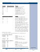
Glossary of Command Notation
Character
String Meaning Allowable Values
u Unit ID 0-3
i Input Number 1-8
o Relay/Output Number 1-8
Set-up Commands
*uCEx - Enable Error and Good Responses - Where x = Y to enable and N = dis-
able. In this mode, when a command is sent that is in error, the unit will reply (pos-
sibly before receiving the entire command) with “EEE.” If the command is sent cor-
rectly, the unit will reply with “RRR.”
Output Control Commands
*uORrL - Latch Output r, output number
*uORrF - Unlatch Output r, output number
*uORrPtt - Pulse Output r, output number. Pulse Length tt: 00-99 corresponds
to 00 - 9.9 Seconds / r. Output number 1 --> 8
*uORrP - Pulse Output r, output number 1 --> 8. Fixed Pulse Length = 700ms