
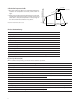
Datasheet

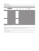


8
F
Ic=1mA
I =20mA
CE
V =2V
Ic=2mA
Ta=25 C
tr
tf
ts
td
0
-30
I =1mA
V =5V
CE
F
Load resistance R (k )
L
Response time ( s
)
Relative current transfer ratio (%
)
Ambient temperature Ta ( C) Ambient temperature Ta ( C)
Collector-emitter saturation voltage
V (sat) (V
)
10
-12
Collector Dark Current I (A
)
Ambient Temperature Ta ( C)
Frequency f (kHz)
Voltage gain Av (dB)
R =10k
L
1k
100
V =2V
Ic=2mA
Ta=25 C
-20
o
0 25 50 75 100
50
100
150
o
-30
0
o
0 20 40 60 80 100
0.02
0.04
0.06
0.08
0.10
0.1
-30
0.1
0.2 0.5 1 2 5 10
0.2
0.5
1
2
5
10
20
50
100
o
0 20 40 60 10080
o
10
10
10
10
10
10
-11
-10
-9
-8
-7
-6
0.2
-10
0
1 520.5
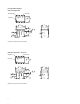
Input
R
Output
Input
R
D
Output
L
Vcc
td
tr tf
ts
90%
10%
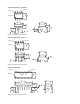
Output
R
D
L
R
Vcc
100010010
Figure 7. Relative Current Transfer Ratio vs. Ambient Temperature
Figure 8. Collector-emitter Saturation Voltage vs. Ambient Temperature
Figure 9. Collector Dark Current vs. Ambient Temperature
Figure 10. Response Time vs. Load Resistance
Figure 11. Frequency Response
Figure 12. Test Circuit for Response Time
Figure 13. Test Circuit for Frequency Response