
Datasheet


2
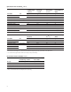
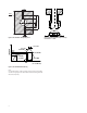
Package Dimensions
Figure 1. ASMT-Ax00 package outline drawing.
Notes:
1. All dimensions in millimeters.
2. Metal slug is connected to anode for electrically non-isolated option.
3. Tolerance is ±0.1 mm unless otherwise specied.
4 . Terminal Finish: Ag plating
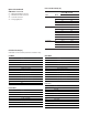
Part Numbering System
Note:
1. Please refer to Page 10 for selection details.
7.4
2.3
Ø 8.0
7.4
1.1
1.5
Ø 6.0
Metal Slug
Anode
Lead
Lens
Cathode
Lead
Body
Metal Slug
13.8 ± 0.2
0.5
4.1 (ref:)
6.0
TOP VIEW
BOTTOM VIEW
3.0
2.0
ASMT – A x 00 – x x
3
x
4
x
5
x
6
Packaging Option
Color Bin Selection
Maximum Flux Bin Selection
Minimum Flux Bin Selection
Dice Type
N – InGaN
A – AllnGaP
Color
R – Red
H – Red Orange
A – Amber
G – Green
C - Cyan
B – Blue
L – Royal Blue
W – Cool White
N – Neutral White
Y – Warm White
1 2