
Datasheet


3
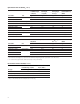
Device Selection Guide (T
j
= 25 °C)
Part Number Color
Luminous Flux (lm) / Radiometric Power (mW),
Φ
V
[1,2]
Test
Current
(mA)
Dice
Technology
Electrically
Isolated
Metal Slug Min. Typ. Max.
ASMT-AR00-ARS00 Red 39.8 50.0 67.2 350 AllnGaP No
[3]
ASMT-AR00-AST00 51.7 65.0 87.4
ASMT-AH00-ARS00 Red Orange 39.8 50.0 67.2 350 AllnGaP No
[3]
ASMT-AA00-ARS00 Amber 39.8 50.0 67.2 350 AllnGaP No
[3]
ASMT-AB00-NMP00 Blue 13.9 20.0 30.6 350 InGaN Yes
ASMT-AL00-NNP00 Royal Blue 275 mW 350 mW 435 mW 350 InGaN Yes
ASMT-AL00-NNQ00 275 mW 355 mW 515 mW
ASMT-AC00-NSU00 Cyan 51.7 75.0 99.6 350 InGaN Yes
ASMT-AG00-NST00 Green 51.7 65.0 87.4 350 InGaN Yes
ASMT-AG00-NUV00 87.4 105.0 113.6
ASMT-AW00-NUV00 Cool White 87.4 90.0 113.6 350 InGaN Yes
ASMT-AW00-NUW00 87.4 100.0 129.5
ASMT-AN00-NUV00 Neutral White 87.4 90.0 113.6 350 InGaN Yes
ASMT-AY00-NTU00 Warm White 67.2 80.0 99.6 350 InGaN Yes
ASMT-AY00-NTV00 67.2 85.0 113.6
ASMT-AY00-NUV00 87.4 95.0 113.6
Notes:
1. Φ
V
is the total luminous ux / radiometric power output as measured with an integrating sphere at 25 ms mono pulse condition.
2. Flux and power tolerance is ±10 %.
3. Electrically isolated metal slug option is also available. Please contact your Avago sale representative.
Absolute Maximum Ratings
Parameter AllnGaP InGaN InGaN Cyan Units
DC Forward Current
[1]
500 500 500 mA
Peak Pulsing Current
[2]
1000 1000 1000 mA
Power Dissipation 1230 1830 1980 mW
LED Junction Temperature 125 135 135 °C
Operating Ambient Temperature Range at 350mA -40 to +115 -40 to +120 -40 to +120 °C
Storage Temperature Range -40 to +120 -40 to +120 -40 to +120 °C
Soldering Temperature Refer to Figure 26
Reverse Volttage
[3]
Not recommended
Notes:
1. Derate linearly based on Figure 10 for AlInGaP and Figure 22 for InGaN.
2. Pulse condition duty factor = 10%, Frequency = 1 kHz.
3. Not designed for reverse bias operation