
Datasheet


2
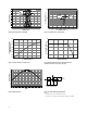
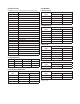
Package Dimensions
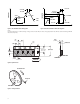
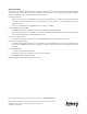
Part Numbering System
NOTES:
1. All Dimensions in millimeters.
2. Tolerance is ± 0.1mm unless otherwise specied.
Device Selection Guide
Part Number
Min. Iv
(mcd)
Typ. Iv
(mcd)
Test Current
(mA) Colors Dice Technology Package Description
ASMT-RR45-AQ902 90.0 120.0 20 Red AlInGaP Untinted, Diused
ASMT-RJ45-AQ502 71.5 130.0 20 Orange AlInGaP Untinted, Diused
ASMT-RF45-AN002 28.0 60.0 20 Yellow Green AlInGaP Untinted, Diused
ASMT-RA45-AP932 57.0 90.0 20 Amber AlInGaP Untinted, Diused
ASMT-RH45-AQ502 71.5 110.0 20 Red Orange AlInGaP Untinted, Diused
Notes:
1. The luminous intensity I
V
is measured at the peak of the spatial radiation pattern which may not be aligned with the mechanical axis of the LED
package.
2. Tolerance: ±15%
0.8
0.45
1.1
0.6
1.6
LED Die
Resin
Lead
Frame
Cathode
Side
0.4
A S M T - R X
1
45 -
Packaging Option
Color Bin Selection
Max. Intensity Bin
Min. Intensity Bin
LED Chip Color
X
2
X
3
X
4
X
5
X
6