
Datasheet


17
Appendix B. Electrical Considerations
Current Calculations
The peak and average display current requirements
have a signicant impact on power supply selection. The
maximum peak current is calculated with Equation 3 in
Table 3.
The average current required by the display can be
calculated with Equation 4 in Table 3.
The power supply has to be able to supply I
PEAK
transients and supply I
LED
(AVG) continuously. The
range on V
LED
allows noise on this supply without
signi cantly changing the display brightness.
V
LOGIC
and V
LED
Considerations
The display uses two independent electrical systems.
One system is used to power the display’s logic and the
other to power the display’s LEDs. These two systems
keep the logic supply clean.
Separate electrical systems allow the voltage applied to
V
LED
and V
LOGIC
to be varied in dependently. Thus, V
LED
can vary from 0 to 5.5 V without aecting either the Dot
or the Control Registers. V
LED
can be varied between 3.1
to 5.5 V without much noticeable variation in light output
to the human eyes. There is also no pixel mismatch
observed.
The intensity of the light output takes a plunge if
operated less than 3.1 V. There is also no pixel mismatch
observed at voltage as low as 2.6 V. However, operating
below 3.1 V is not recommended. Dimming the display by
pulse width modulating V
LED
is also not recommended.
V
LOGIC
can vary from 3.0 to 5.5 V without aecting either
the displayed message or the display intensity. However,
operating below 3 V may change the timing and logic
levels and may cause Dot and Control Registers to be
altered. Thus, operation of the display below 3.0 V is not
recommended.
The logic ground is internally connected to the LED
ground by a substrate diode. This diode becomes
forward biased and conducts when the logic ground
is 0.4 V greater than the LED ground. The LED ground
and the logic ground should be connected to a common
ground, which can withstand the current introduced
by the switching LED drivers. When separate ground
connections are used, the LED ground can vary from
-0.3 V to +0.3 V with respect to the logic ground. Voltages
below -0.3 V can cause all the dots to be ON. Voltage
above +0.3 V can cause dimming and dot mismatch.
Using a decoupling capacitor between the power supply
and ground will help prevent any supply noise in the
frequency range greater than that of the functioning
display from interfering with the display’s internal
circuitry. The value of the capacitor depends on the series
resistance from the ground back to the power supply
and the range of frequencies that need to be suppressed.
It is also advantageous to use the largest ground plane
possible.
Electrostatic Discharge
The inputs to the ICs are protected against static
discharge and input current latch up. However, for best
results, standard CMOS handling precautions should
be used. Before use, the HCMS-39XX should be stored
in antistatic tubes or in conductive material. During
assembly, a grounded conductive work area should be
used and assembly personnel should wear conductive
wrist straps. Lab coats made of synthetic material
should be avoided since they are prone to static
buildup. Input current latch up is caused when the
CMOS inputs are subjected to either a voltage below
ground (V
IN
< ground) or to a voltage higher than
V
LOGIC
(V
IN
> V
LOGIC
) and when a high current is forced
into the input. To prevent input current latch up and ESD
damage, unused inputs should be connected to either
ground or V
LOGIC
. Voltages should not be applied to the
inputs until V
LOGIC
has been applied to the display.
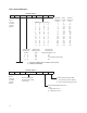
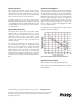
Table 3. Equations.
Equation 1:
T
J
MAX = T
A
+ P
D
* Rθ
JA
Where:
T
J
MAX = maximum IC junction temperature
T
A
= ambient temperature surrounding the display
Rθ
JA
= thermal resistance from the IC junction to ambient
P
D
= total power dissipation
Equation 2:
P
D
= (N * I
PIXEL
* Duty Factor * V
LED
) + I
LOGIC
* V
LOGIC
Where:
P
D
= total power dissipation
N = number of pixels on (maximum 4 char * 5 * 7 = 140)
I
PIXEL
= peak pixel current.
Duty Factor = 1/8 * Osccyc/64
Osc cyc = number of ON oscillator cycles per row
I
LOGIC
= IC logic current
V
LOGIC
= logic supply voltage
Equation 3:
I
PEAK
= M * 20 * I
PIXEL
Where:
I
PEAK
= maximum instantaneous peak current for the display
M = number of ICs in the system
20 = maximum number of LEDs on per IC
I
PIXEL
= peak current for one LED
Equation 4:
I
LED
(AVG) = N * I
PIXEL
* 1/8 * (oscillator cycles)/64
(See Variable Denitions above)