
Datasheet


9
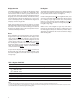
Figure 5. HCMS-39XX write cycle timing diagram
Pixel Map
In a 4-character display, the 160-bits are arranged as 20
columns by 8 rows. This array can be conceptualized as
four 5 x 8 dot matrix character locations, but only 7 of
the 8 rows have LEDs (see Figures 6 & 7). The bottom
row (row 0) is not used. Thus, latch location 0 is never
displayed. Column 0 controls the left-most column.
Data from Dot Latch locations 0-7 determine whether
or not pixels in Column 0 are turned-on or turned-o.
Therefore, the lower left pixel is turned-on when a logic
high is stored in Dot Latch location 1. Characters are
loaded in serially, with the left-most character being
loaded rst and the right-most character being loaded
last. By loading one character at a time and latching
the data before loading the next character, the gures
will appear to scroll from right to left.
NOTE:
1. DATA IS COPIED TO THE CONTROL REGISTER OR THE DOT LATCH AND LED OUTPUTS WHEN CE IS HIGH AND CLK IS LOW.
T
RSS
RSH
T
T
CLKCE CES
T
CLKH
T
CLKL
T
CEH
T
DS
T
DH
T
CEDO
T
DOUT
T
DOUTP
T
PREVIOUS DATA NEW DATA
NEW DATA LATCHED HERE
[1]
CE
RS
CLK
D
IN
LED OUTPUTS,
CONTROL
REGISTERS
D
OUT
S
IMULTANEOUS)
D
OUT
(SERIAL)
3
4
12
5
12
11
6
7
10
8
9