
Datasheet


13
Notes:
1. Each channel.
2. Derate total package power dissipation, P
T
, linearly above 70°C free-air temperature at a rate of 4.5 mW/°C.
3. Duration of output short circuit time should not exceed 10 ms.
4. For single devices, input capacitance is measured between pin 2 and pin 3.
5. Device considered a two-terminal device: pins 1, 2, 3, and 4 shorted together and pins 5, 6, 7, and 8 shorted together.
6. The t
PLH
propagation delay is measured from the 50% point on the leading edge of the input pulse to the 1.3 V point on the leading edge of
the output pulse. The t
PHL
propagation delay is measured from the 50% point on the trailing edge of the input pulse to the 1.3 V point on the
trailing edge of the output pulse.
7. CM
H
is the maximum slew rate of the common mode voltage that can be sustained with the output voltage in the logic high state, V
O
> 2.0 V.
CM
L
is the maximum slew rate of the common mode voltage that can be sustained with the output voltage in the logic low state, V
O
< 0.8 V.
8. For HCPL-2202/12, V
O
is on pin 6.
9. Use of a 0.1 µF bypass capacitor connected between pins 5 and 8 is recommended.
10. In accordance with UL 1577, each optocoupler is proof tested by applying an insulation test voltage ≥4500 V rms for one second (leakage
detection current limit, I
I-O
≤5 µA). This test is performed before the 100% production test for partial discharge (Method b) shown in the IEC/
EN/DIN EN 60747-5-2 Insulation Characteristics Table, if applicable.
11. In accordance with UL 1577, each optocoupler is proof tested by applying an insulation test voltage ≥6000 V rms for one second (leakage
detection current limit, I
I-O
≤5 µA). This test is performed before the 100% production test for partial discharge (Method b) shown in the IEC/
EN/DIN EN 60747-5-2 Insulation Characteristics Table.
12. For HCPL-2231/32 only. Measured between pins 1 and 2, shorted together, and pins 3 and 4, shorted together.
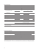
Package Characteristics
Parameter Sym. Min. Typ. Max. Units Test Conditions Fig. Note
Input-Output Momentary V
ISO
3750 V rms RH < 50%, t = 1 min. 5, 10
HCNW22XX 5000 T
A
= 25°C 5, 11
Input-Output Resistance R
I-O
10
12
Ω V
I-O
= 500 Vdc 5
HCNW22XX 10
12
10
13
T
A
= 25°C
10
11
T
A
= 100°C
Input-Output Capacitance C
I-O
0.6 pF f = 1 MHz, 5
HCNW22XX 0.5 0.6 T
A
= 25°C, V
I-O
= 0 Vdc
Input-Input Insulation I
I-I
0.005 µA Relative Humidity = 45%, 12
Leakage Current t = 5 s, V
I-I
= 500 V
Resistance (Input-Input) R
I-I
10
11
Ω V
I-I
= 500 V 12
Capacitance (Input-Input) C
I-I
0.25 pF f = 1 MHz 12
*The Input-Output Momentary Withstand Voltage is a dielectric voltage rating that should not be interpreted as an input-output continuous
voltage rating. For the continuous voltage rating refer to the IEC/EN/DIN EN 60747-5-2 Insulation Characteristics Table (if applicable), your equip-
ment level safety specication or Avago Application Note 1074 entitled “Optocoupler Input-Output Endurance Voltage,” publication number
5963-2203
Withstand
Voltage
*