
Datasheet


2
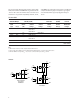
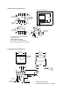
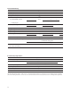
Schematic
HCPL-2201 Schematic
HCPL-2201/02/11/12
HCPL-0201/11
HCNW2201/11
I
F
SHIELD
V
F
V
CC
V
O
GND
I
CC
I
O
+
–
2
3
8
5
I
F1
SHIELD
V
F1
V
CC
V
O1
I
CC
I
O1
+
–
1
2
8
6
HCPL-2231/32
SHIELD
V
F2
V
O2
GND
I
O2
–
+
3
4
5
I
F2
7
The electrical and switching characteristics of the HCPL-
22XX, HCPL-02XX and HCNW22XX are guaranteed from
-40°C to +85°C and a V
CC
from 4.5 volts to 20 volts. Low I
F
and wide V
CC
range allow compatibility with TTL, LSTTL,
and CMOS logic and result in lower power consumption
compared to other high speed couplers. Logic signals
are transmitted with a typical propagation delay of
150 ns.
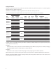
Small- Widebody
Minimum CMR Input 8-Pin DIP (300 Mil) Outline SO-8 (400 Mil) Hermetic
On- Single Dual Single Single Single and
dV/dt Current Channel Channel Channel Channel Dual Channel
(V/µs) V
CM
(V) (mA) Package Package Package Package Packages
1,000 50 1.6 HCPL-2200
[1,2]
HCPL-0201 HCNW2201
HCPL-2201
HCPL-2202
1.8 HCPL-2231
2,500 400 1.6 HCPL-2219
[1,2]
5,000
[3]
300
[3]
1.6 HCPL-2211 HCPL-0211 HCNW2211
HCPL-2212
1.8 HCPL-2232
1,000 50 2.0 HCPL-52XX
[2]
HCPL-62XX
[2]
Notes:
1. HCPL-2200/2219 devices include output enable/disable function.
2. Technical data for the HCPL-2200/2219, HCPL-52XX and HCPL-62XX are on separate Avago publications.
3. Minimum CMR of 10 kV/µs with V
CM
= 1000 V can be achieved with input current, I
F
, of 5 mA.
Selection Guide