
Datasheet


14
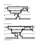
Table 3 shows the calculated maximum allowable ambient
temperature for several dierent sets of operating condi-
tions. The worst case alphanumeric characters (#,@,B)
have 20 pixels. Displaying eight 20-pixel characters will
not occur in normal operation. Thus, using eight 20-pixel
characters to calculate power dissipation will over estimate
the power and the IC junction temperature. The average
number of pixels per character, supply voltage, brightness
level, and number of characters are needed to calculate
the power dissipated by the IC. The ambient temperature,
power dissipated by the IC, and the thermal resistance
are then used to calculate IC junction temperature. The
typical alphanumeric character is 15 pixels. For conditions
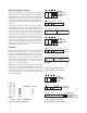
not listed in Table 3, you can calculate the power dissipat-
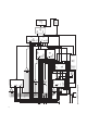
ed by the IC and use Figure 10 to determine the maximum
ambient temperature.
Table 3. Maximum Allowable Ambient Temperature for Various Operating Conditions
AlGaAs Red
Number of Brightness V
DD
I
DD
P
D
Rq
J-A
T
A
MAX
Character Characters Level V mA W °C/W °C
# (20 dots) 8 100% 5.5 408 2.2 39 64
# (20 dots) 8 100% 5.25 387 2.0 39 72
# (20 dots) 8 100% 5.0 366 1.8 39 80
# (20 dots) 7 100% 5.5 357 2.0 39 72
# (20 dots) 6 100% 5.5 306 1.7 39 84
# (20 dots) 8 80% 5.5 327 1.8 39 80
# (20 dots) 8 80% 5.25 310 1.6 39 85
# (20 dots) 8 53% 5.5 216 1.2 39 85
V (12 dots) 8 100% 5.5 228 1.3 39 85
Figure 10. Maximum allowable power dissipation vs. ambient temperature.
T
J
MAX = 150°C or 120°C.
P
D
MAX. – MAXIMUM POWER DISSIPATION – W
50
1.5
T
A
– AMBIENT TEMPERATURE – C
8555 60 80 90
2.3
2.2
2.1
1.8
1.7
1.6
70 7565
2.0
1.9
AlGaAs
Rθ
J-A
= 39C/W
ALL OTHER COLORS
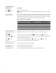
Table 4. Maximum Allowable Ambient Temperature for Various Operating Conditions (cont’d.)
All Colors Except AlGaAs Red
Number of Brightness V
DD
I
DD
P
D
Rq
J-A
T
A
MAX
Character Characters Level V mA W °C/W °C
# (20 dots) 8 100% 5.5 373 2.0 39 72
# (20 dots) 8 100% 5.25 354 1.9 39 77
# (20 dots) 8 100% 5.0 335 1.67 39 85
# (20 dots) 7 100% 5.5 326 1.8 39 80
# (20 dots) 6 100% 5.5 280 1.5 39 85
# (20 dots) 8 80% 5.5 298 1.6 39 85
V (12 dots) 8 100% 5.5 207 1.1 39 85
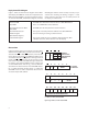
The actual IC temperature is easy to measure. Pin 17 is thermally and electrically connected to the IC substrate. The thermal resistance from pin 17 to
the IC is 16°C/W. The procedure to measure the IC junction temperature is as follows:
1. Measure V
DD
and I
DD
for the display. Measure V
DD
between pins 15 and 16. Measure the current entering pin 15.
2. Measure the temperature of pin 17 after 45 minutes. Use an electrically isolated thermal couple probe.
3. T
J
(IC) = T
pin
+ V
DD
x I
DD
x 16°C/W.