
Datasheet


4
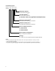
Device
Series
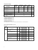
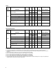
HDSP- Parameter Symbol Min. Typ. Max. Units Test Conditions
Luminous Intensity/Segment
[1,2,5]
I
V
6.9 14.0 mcd I
F
= 20 mA
(Digit Average)
1.8 V I
F
= 20 mA
Forward Voltage/Segment or DP V
F
2.0 3.0 V I
F
= 100 mA
A15x Peak Wavelength λ
PEAK
645 nm
Dominant Wavelength
[3]
λ
d
637 nm
Reverse Voltage/Segment or DP
[4]
V
R
3.0 15.0 V I
R
= 100 µA
Temperature Coefficient of ∆V
F
/°C-2 mV/°C
V
F
/Segment or DP
Thermal Resistance LED Junction- Rθ
J-PIN
255 °C/W/Seg
to-Pin
AlGaAs Red
Electrical/Optical Characteristics at T
A
= 25°C
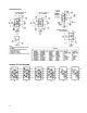
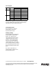
Absolute Maximum Ratings
AlGaAs Red HER/Orange Yellow Green
HDSP-A150 HDSP-7500/-A40X HDSP-7400 HDSP-7800
Description Series Series Series Series Units
Average Power per Segment or DP 96 105 80 105 mW
Peak Forward Current per 160
[1]
90
[3]
60
[5]
90
[7]
mA
Segment or DP
DC Forward Current per 40
[2]
30
[4]
20
[6]
30
[8]
mA
Segment or DP
Operating Temperature Range –20 to +100
[9]
–40 to +100 °C
Storage Temperature Range –55 to +100 °C
Reverse Voltage per Segment or DP 3.0 V
Wave Soldering Temperature for
3 Seconds (1.59 mm [0.063 in.] 250 °C
below Body)
Notes:
1. See Figure 1 to establish pulsed conditions.
2. Derate above 46°C at 0.54 mA/°C.
3. See Figure 6 to establish pulsed conditions.
4. Derate above 53°C at 0.45 mA/°C.
5. See Figure 7 to establish pulsed conditions.
6. Derate above 81°C at 0.52 mA/°C.
7. See Figure 8 to establish pulsed conditions.
8. Derate above 39°C at 0.37 mA/°C.
9. For operation below –20°C, contact your local Avago components sales office or an authorized distributor.