INSTALLATION INSTRUCTIONS AND USER MANUAL VB0052 HEPA Filtration* GSFH1K *Patents pending HEPA Filtration and Fresh Air Ventilation* GSVH1K HEPA Filtration, Fresh Air and Heat Recovery* GSHH3K RESIDENTIAL USE ONLY INSTALLER: LEAVE THIS MANUAL WITH CONSUMER. CONSUMER: USE AND CARE INFORMATION ON PAGES 31 and 35 to 38. www.GuardianPlusAirSystems.com www.Broan-NuTone.com Broan-NuTone LLC 04326 rev 1.
ABOUT THIS MANUAL Congratulations! Your purchase of this whole-house HEPA filtration, with optional ventilation will allow you and your family to enjoy clean and healthy air throughout your home for years to come! Please read this manual thoroughly. Several models are described in this publication. Some details of your unit may be slightly different than the ones shown, as the illustrations are typical ones.
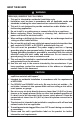
ABOUT THESE UNITS ! WARNING TO REDUCE THE RISK OF FIRE, ELECTRIC SHOCK, OR INJURY TO PERSON(S) OBSERVE THE FOLLOWING: 1. This unit is intented for residential installation only. 2. Installation must be done in accordance with all applicable codes and standards, including fire-rated construction codes and standards. 3. This unit is not designed to provide combustion and/or dilution air for fuel-burning appliances. 4. Do not install in a cooking area or connect directly to an appliance. 5.
TABLE OF CONTENTS 1.0 1.1 2.0 2.1 2.2 3.0 3.1 4.0 4.1 4.2 4.3 5.0 5.1 5.2 5.3 5.4 5.5 5.6 5.7 5.8 5.9 5.10 6.0 6.1 6.2 6.3 6.4 6.5 6.6 7.0 7.1 7.2 7.3 7.4 8.0 9.0 BEFORE STARTING . . . . . . . . . . . . . . . . . . . . . . . . . . . . . . .5 Inspect the Content of the Box . . . . . . . . . . . . . . . .. . 5 TECHNICAL DATA . . . . . . . . . . . . . . . . . . . . . . . . . . . . . . . .5 Dimensions . . . . . . . . . . . . . . . . . . . . . . . . . . . . . . .
1. BEFORE STARTING 1.1 INSPECT THE CONTENTS OF THE BOX ! WARNING To avoid risk of suffocation, discard the plastic bag wrapping the unit. 0 • Inspect the exterior of the unit for shipping damage. Ensure there is no damage to the door, door latches, main switch, etc. CAUTION Remove the cardboard strip inside the unit (if applicable). 1 VD0126 1) Cardboard strip • Inspect the interior of the unit for damage.
2. TECHNICAL DATA (CONT’D) 2.1 DIMENSIONS HEPA FILTRATION UNIT, MODEL GSFH1K 29'' (737 mm) 17.8'' (452 mm) 22.9'' (581 mm) VK0047 FRONT VIEW TOP VIEW HEPA FILTRATION AND HEPA FILTRATION, FRESH AIR FRESH AIR VENTILATION AND HEAT RECOVERY AND MODEL GSHH3K MODEL GSVH1K 29.4'' (748 mm) 17.8'' (452 mm) 22.
2. TECHNICAL DATA (CONT’D) 2.2 MOUNTING AND SERVICING CONSIDERATIONS •The two following pictures are showing the minimum clearance needed to open the door completely. 8” (203 mm) 22” (559 mm) 22.5” (572 mm) 15.75” (400 mm) VD0117 VD0116 NOTES: 1. The unit’s door is removable. For servicing, a minimum of 15” (381 mm) clearance from any obstruction in front of the unit is sufficient to open the door and remove it. 2.
3. PLANNING THE INSTALLATION The Guardian Plus units are versatile appliances capable of delivering filtered air (model GSFH1K) or both filtered and fresh air to your home (models GSVH1K and GSHH3K). Because each installation is different, it is recommended you take the time to plan your installation.
3. PLANNING THE INSTALLATION 3.1 PLANNING OF THE DUCTWORK • Keep it simple. Plan for a minimum of bends and joints. • Keep the length of insulated ducts to the outside of home to a minimum (not for HEPA Filtration model GSFH1K). • Do not ventilate crawl spaces or cold rooms. • If the house has two floors or more, be sure to plan for at least one exhaust register on the highest lived-in level. Use the following table to plan the flexible ducts length.
4. TYPICAL INSTALLATIONS (CONT’D) 4.1 STAND ALONE INSTALLATION (Primarily for homes with no central air mover or equipped with wall furnaces, radiant hot water or electric baseboard heating.) 4.1.1 BASEMENT • Ideal for homes without a central furnace in the basement. Allows filtration and a better air circulation throughout the house. • Easy access to perform the periodic filter maintenance and servicing. • Offers an ambient temperature above freezing (32°F - 0°C).
4. TYPICAL INSTALLATIONS (CONT’D) 4.1 STAND ALONE INSTALLATION (Primarily for homes with no central air mover or equipped with wall furnaces, radiant hot water or electric baseboard heating.) 4.1.2 ATTIC • Ideal for homes without a central furnace, or limited space applications, allows filtration and a better air circulation throughout the house. • Only one partition to go through to install the registers. • No visible ducts.
4. TYPICAL INSTALLATIONS (CONT’D) 4.1 STAND ALONE INSTALLATION (Primarily for homes with wall furnaces, radiant hot water or electric baseboard heating.) 4.1.3 GARAGE CLOSET • Ideal for homes without a central furnace, or limited space applications, allows filtration and a better air circulation throughout the house. • Easy access to perform the periodic maintenance (twice a year). • The HEPA Filtration model GSFH1K has no connection to outside, so all parts encircled are not required.
4. TYPICAL INSTALLATIONS (CONT’D) 4.2 CENTRAL DRAW POINT INSTALLATION (Connection to a Forced Air System) 4.2.1 BASEMENT • Simplified installation by using the home’s existing ductwork to supply filtered air throughout the house. • The central draw point should be located in the main area where most of the pollutants are produced. • The furnace/air handler does not need to run continuously. • Easy access to perform the periodic maintenance. • Offers an ambient temperature above freezing (32°F - 0°C).
4. TYPICAL INSTALLATIONS (CONT’D) 4.3 RETURN-TO-RETURN INSTALLATION (Connection to a Forced Air System) 4.3.1 CRAWL SPACE • Simplify the installation by using the existing ductwork. • Non-visible ducts. • The HEPA Filtration model GSFH1K has no connection to outside, so all parts encircled are not required. CAUTION When the ambient temperature for the unit location is below freezing (32°F - 0°C), the unit must run continuously to prevent condensation.
5. INSTALL THE UNIT 5.
5. INSTALL THE UNIT (CONT’D) 5.4 FOR SUSPENDED APPLICATIONS Use the four chains and springs in the hardware pack provided with the unit. According to your needs and model type, you can install the unit either in a vertical or horizontal position. VERTICAL POSITION - ALL MODELS HORIZONTAL POSITION (LEFT ALL MODELS SIDE) HORIZONTAL POSITION (RIGHT SIDE) MODELS GSFH1K AND GSVH1K ONLY VD0075 VD0076 CAUTION Make sure the unit is level.
5. INSTALL THE UNIT (CONT’D) 5.4 FOR SUSPENDED APPLICATIONS (CONT’D) • Insert the four hooks in the square holes and fix them to the unit using four screws #8 - 32 x 3/4”. NOTE: To wire the wall control, go to Section 6.2 to 6.4. • Reinstall the front plate and the door. VO0020 • Hang the unit to the joists, using four #8 x 1 1/2” screws, four chains and four spings. See illustration. VD0077 5.5 INSTALLING 8’’ DUCTS AND REGISTERS 5.5.1 STAND ALONE SYSTEM (AS ILLUSTRATED IN SECTION 4.
5. INSTALL THE UNIT (CONT’D) 5.5 INSTALLING 8’’ DUCTS AND REGISTERS 5.5.1 STAND ALONE SYSTEM (AS ILLUSTRATED IN SECTION 4.1) How to connect the 8’’ flexible duct to the registers and unit’s duct connector. • Once the register location is determined, cut out a 10-1/4’’ x 6-7/8’’ (260 mm x 175 mm) hole. Run one end of the 8’’ flexible duct through the hole and fix it to the duct connector (1), using a 30’’ tie wrap and duct tape.
5. INSTALL THE UNIT (CONT’D) 5.5 INSTALLING 8’’ DUCTS AND REGISTERS (CONT’D) 5.5.2 CENTRAL DRAW POINT (AS ILLUSTRATED IN SECTION 4.2) Stale air ductwork Same as for Stand Alone System, described in point 5.5.1. Filtered air ductwork (Return side connection) 0 ! WARNING When performing duct connections, always use approved tools and materials. Respect all corresponding laws and/or safety regulations. Please refer to your local building code. Use only UL listed duct tape.
5. INSTALL THE UNIT (CONT’D) 5.5 INSTALLING 8’’ DUCTS AND REGISTERS (CONT’D) 5.5.3 RETURN-TO-RETURN (AS ILLUSTRATED IN SECTION 4.3) ! WARNING When performing duct connections, always use approved tools and materials. Respect all corresponding laws and/or safety regulations. Please refer to your local building code. Use only UL listed duct tape. 0 Filtered air ductwork (Return side connection) Same as for Central draw Point, described in point 5.5.2.
5. INSTALL THE UNIT (CONT’D) 5.6 INSTALLING INSULATED FLEXIBLE DUCTS (GSVH1K AND GSHH3K MODELS ONLY) (CONT’D) NOTE: If there is not sufficient space to install the Tandem transition®, both optional single exterior hood and AirDuo™ exterior hood must be used. Identify each insulated duct. For fresh air from outside duct, use the blue sticker dots (one dot at each end). For exhaust air to outside duct, use the red sticker dots (one dot at each end). Then, go to Point 5.6.2 and then go to Section 5.8. 5.
5. INSTALL THE UNIT (CONT’D) 5.6 INSTALLING INSULATED FLEXIBLE DUCTS (GSVH1K AND GSHH3K MODELS ONLY) (CONT’D) 5.6.2 CONNECTION TO THE 5’’ TO 6’’ OVAL PORTS OF THE UNIT (CONT’D) 2. Connect the interior flexible duct to the port using a 24’’ tie wrap. VJ0017 3. Pull the insulation over the joint and tuck it between the inner and outer rings of the port. Pull the vapor barrier over the insulation and over the outer ring of the port. VJ0018 4.
5. INSTALL THE UNIT (CONT’D) 5.7 INSTALLING AIRDUO™ EXTERIOR HOOD* (GSVH1K AND GSHH3K MODELS ONLY) 5.7.1 ASSEMBLING AIRDUO™ EXTERIOR HOOD AIRDUO™ exterior hood requires assembly. Assemble the top metal screen, the plastic grille and the bottom metal screen to the dual exterior hood. Use provided screws. See illustration beside. *Patent pending VO0024 5.7.
5. INSTALL THE UNIT (CONT’D) 5.7 INSTALLING AIRDUO™ EXTERIOR HOOD* (GSVH1K AND GSHH3K MODELS ONLY) (CONT’D) 5.7.4 CONNECTING TANDEM® TRANSITION TO AIRDUO™ EXTERIOR HOOD 1 1. Using a jigsaw, cut a 6’’ diameter hole in the exterior wall and insert the Tandem® transition through this hole. VD0084 1) EXHAUST AIR TO OUTSIDE duct CAUTION The Tandem® transition must be inserted in such a way that the EXHAUST AIR TO OUTSIDE duct will be located on the top.
5. INSTALL THE UNIT (CONT’D) 5.8 INSTALLING TWO EXTERIOR HOODS* (GSVH1K AND GSHH3K MODELS ONLY) 5.8.1 ASSEMBLING EXTERIOR HOODS Both exterior AirDuo™ hood and optional exterior single hood require assembly. Assemble the top metal screen, the plastic grille and the bottom metal screen to the AirDuo™ exterior hood*. Use provided screws. Slide the bottom metal screen into the single exterior hood base. See following illustrations.
5. INSTALL THE UNIT (CONT’D) 5.8 INSTALLING TWO EXTERIOR HOODS* (GSVH1K AND GSHH3K MODELS ONLY) (CONT’D) 5.8.3 LOCATING THE AIRDUO™ EXTERIOR HOOD ! WARNING Make sure this hood is at least 3’ (0.9 m) away from any of the following: 0 • • • • High efficiency furnace vent. Gas meter exhaust, gas barbecue-grill. Any exhaust from a combustion source. Garbage bin and any other source of contamination.
5. INSTALL THE UNIT (CONT’D) 5.8 INSTALLING TWO EXTERIOR HOODS* (GSVH1K AND GSHH3K MODELS ONLY) (CONT’D) CAUTION The exterior backplate must be installed with the word ‘’TOP’’ pointing upward. 5.8.4 CONNECTING INSULATED DUCTS TO EXTERIOR HOODS (CONT’D) 2. Pull back the insulation to expose the flexible duct and, using a tie wrap, attach it to the inner ring of the exterior backplate (5’’ ring for the 5’’ insulated ducts or 6’’ ring for the 6’’ insulated ducts). Carefully seal with duct tape (A).
5. INSTALL THE UNIT (CONT’D) 5.9 CONNECTING THE DRAIN (GSHH3K MODEL ONLY) 1 2 slide 3 1 1 VO0025 VO0046 1. Remove the door by turning the switch knob to the OFF position (to unlock the door).Then, unlatch the door, open and slide it out of its hinge. Slide out the core assembly to access the 2 drain fitting hole locations (1). Punch out the holes. 2 2. Hand tighten the two plastic drain fittings (1) using the gaskets (2) and nuts (3) as shown. (Items 1 to 3 are provided).
5. INSTALL THE UNIT (CONT’D) 5.10 LOW TEMPERATURE APPLICATIONS BELOW FREEZING (32°F OR 0°C) ALL MODELS CAUTION When the ambient temperature surrounding the unit falls below freezing (32°F or 0°C), all units must run continuously to prevent condensation. FOR GSHH3K HEAT RECOVERY MODEL ONLY CAUTION • When installing an GSHH3K HEPA Filtration, Fresh Air and Heat Recovery model, make sure the unit’s cabinet and its drain line are protected from freezing. • Install a drip pan if required by local code.
5. INSTALL THE UNIT (CONT’D) 5.10 FOR LOW TEMPERATURE APPLICATIONS BELOW FREEZING (32°F OR 0°C) (CONT’D) 5.10.1BLANKET INSULATION (CONT’D) Wrap the unit as shown. Make sure that all joints are fully sealed to prevent cold air penetration between the insulation and the unit. 1 3 2 VR0002 NOTES: 1. Holes must be done in the insulation blanket to allow drain line installation for model GSHH3K. 2. MAKE SURE to use excess insulation to cover the top of unit and its ports. 5.10.
6. CONTROLS 6.1 MAIN SWITCH All units are equipped with a 3-position main switch, located on the front panel. The unit is intented for use with a wall controller (provided, see below). The main switch is to remain in either the “OFF” or “Normal/Remote” modes ONLY. The “Normal/Remote” mode allows the homeowner to operate the product from the wall controller, typically mounted near a thermostat or other convenient location. NORMAL/REMOTE: UNIT IS OPERATING ON NORMAL SPEED.
6. CONTROLS (CONT’D) 6.4 INSTALLATION OF THE WALL CONTROLLERS (BOTH MODELS) ! WARNING Always disconnect power to the unit before making any connections. Failure in disconnecting power could result in electrical shock or damage of the wall control or electronic module inside the unit. 0 CAUTION Never install more than one optional wall controller per unit. 1. Determine a convenient location for the control. 2. Remove the controller’s cover plate (1).
6. CONTROLS (CONT’D) 6.4 INSTALLATION OF THE WALL CONTROLLERS (BOTH MODELS) (CONT’D) 6. Reinstall the cover plate. Using provided wall anchors and provided screws, mount the wall controller on the wall. Use only 2 screws to mount on outlet box. See illustrations below.
6. CONTROLS (CONT’D) 6.4 INSTALLATION OF THE WALL CONTROLLERS (BOTH MODELS) (CONT’D) 8. Looking inside the right side front port, you gain access the field wiring terminals for the controller. Remove the side door located on the electrical box and punch out its knock out. Run the cable through the knock-out hole and connect each wire to their corresponding terminal (YELLOW in “Y’’, RED in “R’’, GREEN in “G’’ and BLACK in “B’’).
6. CONTROLS (CONT’D) 6.5 OPERATING ACCGSC1 POWER CONTROLLER INDICATOR: BOOST: LIGHTS UP WHEN SLIDE UNIT NORMAL BOOST POSITION. SWITCH IS IN THE OR FILTER IS OPERATING AT ITS HIGH SPEED. MAINTENANCE NORMAL: INDICATOR: UNIT FLASHES EVERY MINUTE TO IS OPERATING AT ITS NORMAL SPEED. INDICATE IT IS ON DUTY. FLASHES EVERY SECOND WHEN IT IS TIME TO OFF: UNIT IS OFF. REPLACE PREFILTER. LED STAYS LIT WHEN IT IS VC0047 TIME TO REPLACE FILTER RESET AND PREFILTER.
7. MAINTENANCE ! WARNING Risk of electrical shocks. Before performing any maintenance or servicing, always disconnect the unit from its power source. 0 7.1 SEMI-ANNUAL MAINTENANCE (ESSENTIAL) Your wall controller (ACCGSC1 or ACCGSC3) tells you when to perform this maintenance when the Filter Maintenance light is flashing. Otherwise, maintenance should be performed every six months to ensure proper operation for years to come. Follow these steps: 1. Turn switch knob to OFF to unlock the door. 2.
7. MAINTENANCE (CONT’D) 7.1 SEMI-ANNUAL MAINTENANCE (ESSENTIAL) (CONT’D) 4. Using your thumbs, push on the prefilter side to disengage it from the filter cartridge. Then, slide it out of the filter cartridge and discard it. Install the new prefilter by reversing this operation. 1 2 VD0092 VD0093 1) Filter cartridge 2) Prefilter 5. Clean the inside walls of the unit with a clean damp cloth, then wipe with a dry one.
7. MAINTENANCE (CONT’D) 7.2 ANNUAL MAINTENANCE (ESSENTIAL) Your unit is equipped with a wall controller (ACCGSC1 or ACCGSC3), which tells when to perform maintenance when the Filter Maintenance light stays ON. Otherwise, this maintenance must be performed once a year to ensure your unit proper operation for years to come. Proceed as the Semi-annual Maintenance (Section 7.1), but instead of replacing the prefilter (point 4), discard the complete HEPA Filter cartridge (including prefilter).
8. TROUBLESHOOTING PROBLEMS SOLUTIONS 1.Unit does not start at Normal or Boost position. • Check breaker or fuse in main distribution panel. • Check there is 120V at the electrical outlet. • Make sure the unit main switch is properly set in Normal or Boost position. • If a wall control (ACCGSC1 or ACCGSC3) is connected, disconnect control wire from the unit, then make sure the unit main switch is properly set in Normal or Boost position.
9. WARRANTY WHOLE-HOUSE AIR FILTRATION SYSTEM WARRANTY Broan-NuTone warrants to the original consumer purchaser of its products, that such products will be free from defects for a period of two (2) years, from date of original purchase. THERE ARE NO OTHER WARRANTIES, EXPRESS OR IMPLIED, INCLUDING, BUT NOT LIMITED TO, IMPLIED WARRANTIES OF MERCHANTABILITY OR FITNESS FOR A PARTICULAR PURPOSE.