
Instructions / Assembly


Page 2
VENTILATION FAN / LIGHT MODEL QTN130LE1
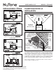
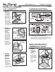
PLAN THE INSTALLATION
Cooking
Equipment
Floor
COOKING AREA
Do not install above or
inside this area.
45
o
45
o
NOT FOR USE IN
A COOKING AREA.
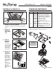
TYPICAL
INSTALLATIONS
Housing mounted to I-joists.
Use I-joist spacer block (provided).
Housing mounted to joists.
Housing mounted to truss.
To mount housing anywhere between joists, i-joists or trusses, use
optional hanger bar kit MHB4 (sold separately). Follow mounting
instructions included with kit.
OPTIONAL MHB4
HANGER BARS
(span up to 24”)
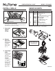
ROOF CAP*
(with built-in
damper)
WALL CAP*
(with built-in
damper)
6-IN. or 4-IN.
ROUND
ELBOWS*
6-IN. or 4-IN. ROUND
DUCT*
FAN
HOUSING
Seal gaps
around
housing.
Seal duct
joints with
tape.
Keep duct
runs short.
INSULATION
(Place around and
over fan housing.)
POWER
CABLE*
*Purchase
separately.
OR
The ducting from this fan to the outside of the building has a strong effect on the
air flow, noise and energy use of the fan. Use the shortest, straightest duct routing
possible for best performance, and avoid installing the fan with smaller ducts than
recommended. Insulation around the ducts can reduce energy loss and inhibit
mold growth. Fans installed with existing ducts may not achieve their rated airflow.
6” round metal duct is recommended for best performance.