
User's Manual


Page6
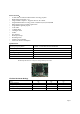
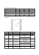
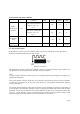
Recommended Operation Conditions
Parameter PIN
Conditions MIN Tym MAX UNIT
Battery
(VDD_BAT)
operation
V
DD
VDD5V and VDDL
open circuit, temperature
range in - 40 ℃ to +
85 ℃
3.0 5.5 V
VDD5V and VDDL
short circuit, temperature
range in - 40 ℃ to +
85 ℃
2.0 3.6 V
Operating
temperature
range
T
OP
-40 85
℃
Supply
voltage slope
1
mV/us
2.3 PCB antenna designs
PCB antenna is widely used in short distance remote control and communication. This part outlines
Printed Circuit Board (PCB) antennas used by CSR.
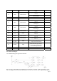
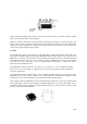
Meander Line Antenna
The length of the meander line antenna is difficult to predict. It is usually a bit longer than a quarter wave
but dependent on its exact geometry and proximity to the ground plane.
Note:
In Figure 3 the ground plane is shown in black. S is the distance from the ground plane. See Figure 5 for
approximate dimensions.
This type of antenna is always a PCB version. The antenna is printed on the top layer and a ground plane
is placed near the antenna on the top layer. There must be no ground plane underneath the radiating
section of the antenna.
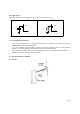
The real part of the impedance of this antenna is about 15-25W, depending on geometry and proximity to
the ground plane. The impedance matching is done by adjusting the length of the antenna until the input
impedance is at the unity conductance circle (when normalised to 50W), in the top half of the Smith chart
(Point A). A shunt capacitor is then connected between the antenna input and ground to match to 50W
(Point B). Experimental measurement is used to determine the correct design.