
Manual


AP1 & RP SERIES
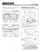
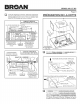
[_ Use the diagram below, for placement of ductwork
proper
and electrical cutout in cabinet or wall. For a non-ducted
installation, DO NOT cut a duct access hole.
31/4"X 10"
HOOD MOUNTING SCREWS (4) VERTICAL DUCTING
121¼'' (30" hood) /121¼" (30" hood) ====_
_J=== 1 " . 1 n .
15_ (36 hood)_15_ (36 hood)
F CAB! l
| 6 /8" BOTTOM _=====7 2"=-_ / I "
/ _,.--_'_/9÷,8,, /
105,8,,I vERT,oA,ooo_I11 IJ_! 9"
t ELECTRICAL
WOOD SHIMS ACCESS HOLE
(recessed-bottom CENTER
cabinets only) LINE (in cabinet bottom)
WOOD SHIMS
(recessed-bottom
cabinets only)
,====_
I
/
\
\
MOUNTING
l 3¼" X I0"HORIZONTAL DUCTING
SCREWS (4)
CABINET FRONT 3/4"
lJ8"1 J Ii
_--- ! L !
'T 'i °
3718,, HORIZONTAL DUCT I T
CABINETJL ACCESS HOLE J
I._,,,==61,,/4_== 61,,/4'L==_
BOTTOM
12¼" (30" hood) _. 71/2"
,== ,, _ 12¼ (30"hood)
15¼" (36 hood) I i5Y:" <36" hood)
HOOD _,
CENTER
LINE
ELECTRICAL
ACCESS HOLE
(in wall)
Page 3
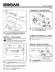
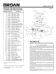
PREPARE THE HOOD
WIRING
COVER
I
= i ! =
AL_UMINUM
I
FILTERS '
Remove the Aluminum Filters. Bottom and
Cover,
Wirinq Cover from the hood.
f VERTICAL DISCHARGE POSITION
-- BLOWER
_.__ /"-_----?".. _ MOUNTING
_'_':', I _<_ ROD <2)
HORIZONTAL DISCHARGE POSITION
-,-IT
BLOWER
i _i i -- _ _ _ I _ MOUNTING
[!1
Blower is shipped in Vertical Dischar_cLe_Position.
To change blower to Horizontal Dischar_cLe_Position:
Remove Knurled Nuts from Blower Mountin_ Rods.
Disengage mounting rods from blower and rotate blower
to horizontal discharge position. Re-engage mounting
rods and tighten blower in place with knurted nuts.