USER AND INSTALLER MANUAL B110H65RT* B110H65RS* B130H65RT* B130H65RS* B130E65RT B130E65RS B150H75NT* B150H75NS* B160H75RT* B160H75RS* B160H65RT* B160H65RS* B160E65RT B160E65RS VB0288 REGISTER YOUR PRODUCT ONLINE AT: www.broan-nutone.com/en-us/home/customer-service/product-registration For additional information, visit www.Broan-NuTone.
Please take note that this manual uses the following symbols to emphasize particular information: ⚠ WARNING Identifies an instruction which, if not followed, might cause serious personal injuries including possibility of death. CAUTION Denotes an instruction which, if not followed, may severely damage the unit and/or its components. NOTE: Indicates supplementary information needed to fully complete an instruction. LIMITATION For residential (domestic) installation only.
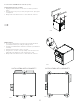
TABLE OF CONTENTS 1. TECHNICAL DATA...................................................................................................................... 4 1.1 AIR DISTRIBUTION (NORMAL OPERATION) ...............................................................................................................4 2. INSTALLATION .................................................................................................................................... 4 2.1 LOCATING AND MOUNTING THE UNIT.................
Consumer Information A. To ensure quiet operation of the ENERGY STAR certified H/ERV, each product model must be installed using sound attenuation techniques appropriate for the installation. B. The way your heat/energy-recovery ventilator is installed can make a significant difference to the electrical energy you use. To minimize the electricity use of the heat/energy-recovery ventilator, a stand-alone fully ducted installation is recommended.
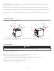
2.1 LOCATING AND MOUNTING THE UNIT (CONT.) Suspended to the joists or trusts: • Slightly bend the brackets on the unit to insert the provided chains. • Hang the unit to the joists (or trusts) using the chains. Springs are not required. • Always make sure that the unit is no more than 1/4" off level. OR VD0485 Wall mounted: • Choose the appropriate location(s) for the mounting brackets (see illustration below) according to stud(s) position.
2.2 INSTALLING THE DUCTWORK AND THE REGISTERS ! WARNING Never install a stale air exhaust register in a room where there is a combustion device, such as a furnace, gas water heater, fireplace or any appliance or equipment that can generate gaseous contaminants, or pollutants. The negative pressure this could create in the room may impair proper evacuation of the gas or pollutants, which may have severe health consequences. 2.2.
2.2.3 SIMPLIFIED INSTALLATION (T-4) CAUTION The central forced-air system must be synchronized with the unit since fresh air evacuation and distribution come from the same section. The central forced-air system must operate to avoid fresh air to be directly drawn by the evacuation, which would reduce significantly fresh air supply to the building. See Section 3.3 for ducting. ! WARNING Duct connection to the central forced-air system can be regulated by some codes and standards.
2.3 CONNECTING THE DRAIN (HRV ONLY) CAUTION Install the drain hose included and run it to a drain or a pail. This unit may generate a large amount of water in cooler weather. It is necessary to install the drain hose properly to prevent water damage and/or material damage. • • • • • • • • Cut the appropriate length of drain tubing (see illustrations below). Connect the tubing to the provided adaptor.
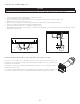
2.5 INSTALLING THE EXTERIOR HOODS EXHAUST HOOD Choose an appropriate location for the exterior hoods: INTAKE HOOD • At least 6 feet between both hoods to avoid cross-contamination • At least 18 inches away from the ground 6” ø 18” ! WARNING 6’ Make sure intake hood is at least 6 feet (1.
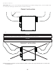
2.6.1 DUCTS CONNECTION IMPORTANT: Make sure to connect ducting as illustrated below to get airflows reading accuracy. Correct installation will also allow proper drainage of water that may accumulate in ducting. CORRECT INSTALLATION R = 3" minimum VD0489 CAUTION Ducting must not be too crushed. Otherwise, airflows reading accuracy will be affected. CAUTION Insulated ducts must have the same diameter as the ports to ensure proper drainage of water that may accumulate in ducts.
3. CONNECTIONS 3.1 ELECTRICAL CONNECTION TO OPTIONAL MAIN WALL CONTROL ! WARNING Always disconnect the unit before making any connections. Failure to cut power could result in electrical shock or damage to the wall control or electronic module inside the unit. CAUTION Never install more than one optional main wall control per unit. Make sure that the wires do not short-circuit between themselves or by touching any other components on the wall control. Avoid poor wiring connections.
3. CONNECTIONS (CONT’D) 3.2 ELECTRICAL CONNECTION TO OPTIONAL AUXILIARY WALL CONTROL 3.2.
120VAC GRN 60Hz W1 1 J1 WHT J2 F3 F2 J3 F5 F4 Motor Fuses 1 M2 (Supply ) GRN Line voltage factory wiring Low voltage factory wiring Low voltage field wiring 5A/125VAC F1 1 M1 BLU BLK BLK BLACK BLU BLUE GRN GREEN RED RED WHT WHITE WIRING COLOR CODE BLK RED (Exhaust ) BLU BLK GRN RED Ventilation Fan Motors J5 M2 J6 1 Recirculation Damper(J6 ) is not present for all models 1 M3 J14 Serial Number 1 J15a J7a R1 Thermistor LCD ASSEMBLY A2 * Optional Central Forced
5. UNIT AUTO-BALANCING PREPARATION Follow these steps to ensure accurate measurements: • Seal all the ductwork with tape. Close all windows and doors. • Turn off all exhaust devices such as range hood, dryer and bathroom fans. • If the installation is in any way connected to a ductwork of a central forced-air system, make sure that the central forced-air system blower is ON. If not, leave central forced-air system blower OFF. AUTO-BALANCING PROCEDURE 1. 2. 3. 4. 5.
7.
7.
8. INSTALLER’S TROUBLESHOOTING ! WARNING The wearing of safety glasses and gloves is recommended since a few diagnosis procedures may require the unit to be in operation while proceeding. Be careful with moving and live parts to prevent any risk of injury. ERROR DESCRIPTION SOLUTION E01 Supply damper range STEP 1: Unplug unit, inspect the damper system, remove any undesirable obstacle or dirt (filters and core may have to be removed to access the damper system). Plug unit.
8. INSTALLER’S TROUBLESHOOTING (CONT’D) ERROR DESCRIPTION SOLUTION E26 Supply motor (drive over temp) STEP 1: Validate if the air exchanger is exposed to ambient temperatures within the operating limits (see p. 4) If STEP 1 did not fix the problem, perform STEP 2: Replace the electronic assembly. E32 Exhaust airflow STEP 1: Perform a visual inspection of the exhaust damper system. Clean filters, distribution registers and outside supply hood. Inspect ducting to ensure it is not squeezed or bent.
8. INSTALLER’S TROUBLESHOOTING (CONT’D) WARNING DESCRIPTION SOLUTION W22 Supply airflow STEP 1: Perform a visual inspection of the supply damper system. Clean filters, distribution registers and outside supply hood. Inspect ducting to ensure it is not squeezed or bent. If STEP 1 did not fix the problem, perform STEP 2: Remove ducting of the supply path. On the LCD screen, select MAX to check if the unit is able to reach the selected flow. If so, review the ducting path.
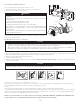
9. MAINTENANCE ! WARNING High voltage risk. During maintenance or repairs, always stop the unit then unplug it to prevent any risk of electric shock. The wearing of safety glasses and gloves is recommended when handling unit components to prevent any risk of injury that could be caused by the presence of thin metal. 9.1 QUARTERLY 1. 2. 3. 4. Disconnect power cord. The door of this unit is hinged and maintained closed by 2 latches. Open them and set aside. Clean the inside of the door with a damp cloth.
9. MAINTENANCE (CONT’D) 9.2 ANNUAL (AT FALL) 1. Repeat steps 1 to 6 from the previous section and continue with the following steps: CAUTION • 2. Handle the recovery core with care. Clean the recovery core: VD0494 HRV MODELS • • • • 3. 4. 5. 6. ERV MODELS Remove the core. Remove the dust on the core using a vacuum cleaner and a Let it soak in a mixture of cold or lukewarm water and mild soft brush attachment. soap (dishwashing liquid). CAUTION: DO NOT SOAK THE ENERGY RECOVERY Rinse thoroughly.
11. WARRANTY This ventilation unit is a high quality product, built and packaged with care. The manufacturer warrants to the original purchaser of its product, that such products will be free from defects for the period stated below, from date of original purchase. For all units, the warranty covers parts only against any operational defect. This 5-year warranty is subject to performance of the core maintenance according recommendations in this manual.
MANUAL DEL USUARIO Y DEL INSTALADOR B110H65RT* B110H65RS* B130H65RT* B130H65RS* B130E65RT B130E65RS B150H75NT* B150H75NS* B160H75RT* B160H75RS* B160H65RT* B160H65RS* B160E65RT B160E65RS VB0288 REGISTRE SU PRODUCTO EN LÍNEA EN: www.broan-nutone.com/en-us/home/customer-service/product-registration Para obtener más información, visitar nuestro sitio www.Broan-NuTone.
Este manual utiliza los siguientes símbolos para hacer hincapié en determinada información: ⚠ ADVERTENCIA Se refiere a una instrucción que, si no se sigue, puede provocar lesiones personales graves, incluso causar la muerte. PRECAUCIÓN Denota una instrucción que, si no se sigue, puede dañar gravemente el aparato y/o sus componentes. NOTA: Indica la información complementaria necesaria para completar una instrucción. LIMITACIÓN Para instalación residencial (doméstica) solamente.
ÍNDICE 1. DATOS TÉCNICOS ...................................................................................................................... 4 1.1 DISTRIBUCIÓN DEL AIRE (FUNCIONAMIENTO NORMAL) ............................................................................. 4 2. INSTALACIÓN ............................................................................................................................. 4 2.1 UBICACIÓN Y MONTAJE DEL APARATO ........................................................
Información al usuario A. Para asegurar un funcionamiento silencioso del HRV/ERV certificado ENERGY STAR, cada modelo de aparato debe instalarse utilizando técnicas de atenuación acústica adecuadas para la instalación. B. La forma en que se instala su ventilador de recuperación de calor/energía puede hacer una diferencia significativa a la energía eléctrica consumida.
2.1 UBICACIÓN Y MONTAJE DEL APARATO (CONT.) Suspendido en las viguetas: • Doble ligeramente los soportes del aparato para insertar las cadenas provistas. • Cuelgue el aparato en las viguetas utilizando las cadenas. Los resortes no son necesarios. • Asegúrese siempre de que el desnivel del aparato no sea superior a 1/4 pulg. O VD0485 Montado en la pared: • Seleccione la(s) ubicación/ubicaciones apropriada(s) para los soportes (véase la ilustración a continuación) según la posición de los montantes.
2.2 INSTALACIÓN DE LOS CONDUCTOS Y REGISTROS ! ADVERTENCIA No instale nunca un registro de salida de aire viciado en una habitación donde haya un dispositivo de combustión, tal como una caldera, un calentador de agua a base de gas, una chimenea o cualquier dispositivo o equipo que pueden producir gases contaminantes o otros tipos de contaminantes.
2.2.3 INSTALACIÓN SIMPLIFICADA (T-4) PRECAUCIÓN El sistema central de aire forzado debe estar sincronizado con el aparato porque la evacuación y la distribución de aire fresco proceden de la misma sección. El sistema central de aire forzado debe funcionar para evitar que el aire fresco sea directamente aspirado por la evacuación, lo que reduciría considerablemente el aporte de aire fresco al edificio. Véase la sección 3.3 por la conexión.
2.3 CONEXIÓN DEL DESAGÜE (HRV SOLAMENTE) PRECAUCIÓN Instalar el conducto de desagüe incluido y canalizarlo hacia un dren o un balde. Este aparato puede generar una gran cantidad de agua cuando hace frío. Es necesario instalar el conducto de desagüe adecuadamente para evitar todo daño y/o rotura de material. • • • • • • • • Corte la longitud apropriada de conducto de desagüe (véase las ilustraciones a continuación). Conecte el conducto al adaptador suministrado.
2.5 INSTALACIÓN DE LAS BOCAS EXTERIORAS BOCA DE Elija un lugar adecuado para las bocas exteriores: 6 PULG. ø SALIDA • Debe haber al menos 6 pies entre ambas bocas para evitar la contaminación cruzada. • Debe haber una distancia mínima de 18 pulg. hasta el suelo. BOCA DE ADMISIÓN 18 PULG.
2.6.1 CONEXIÓN DE LOS CONDUCTOS IMPORTANTE: Asegúrese de conectar los conductos como se ilustra a continuación para obtener una lectura precisa de los flujos de aire. Una instalación correcta también permitirá un drenaje adecuado del agua que se pueda acumular en los conductos. INSTALACIÓN CORRECTA R = 3 pulg. mínimo VD0489 PRECAUCIÓN Los conductos no deben estar demasiado aplastados. De lo contrario, la precisión de los flujos de aire será afectada.
3. CONEXIONES 3.1 CONEXIÓN ELÉCTRICA CON EL CONTROL MURAL PRINCIPAL OPCIONAL ! ADVERTENCIA Desconecte siempre el aparato antes de efectuar cualquier conexión. De no cortar la alimentación, podría producirse un choque eléctrico o dañarse el control mural o el módulo electrónico dentro del aparato. PRECAUCIÓN No instale nunca más de un control mural principal opcional por aparato. Compruebe que los cables no se cortocircuiten entre ellos o tocando otros componentes del control mural.
3. CONEXIONES (CONT.) 3.2 CONEXIÓN ELÉCTRICA CON EL CONTROL MURAL AUXILIAR OPCIONAL 3.2.
120VCa 60Hz W1 Tierra 1 B J1 J2 AZ NE 1 AZ B NE R V M2 F3 F2 J3 * Opcional 1 J6 M3 AZUL BLANCO NEGRO ROJO VERDE 1 MCU J7 M4 1 A1 J9 J14 Número de serie J13 K1 Relé sistema central de aire forzado 1 J15a J7a R1 Termistor CONJUNTO LCD A2 * Cableado opcional sistema central de aire forzado (24VCA aislado) V YW CGf G R Luz LED CONJUNTO ELECTRÓNICO PRINCIPAL GND D+ D12V LED OVR Cableado de los controles principales y auxiliares Transformador de aislamiento La compuerta d
5. AUTO BALANCEO DEL APARATO PREPARACIÓN Siga estas indicaciones para mediciones precisas: • Obture todos los conductos con cinta adhesiva. Cierre todas las ventanas y puertas. • Apague todos los dispositivos de extracción, coma la campana de cocina, la secadora y los ventiladores del baño. • Si la instalación está de alguna manera conectada a un conducto de un sistema central de aire forzado, asegúrese de que el ventilador impelente del sistema central de aire forzado esté encendido.
7. PIEZAS DE RECAMBIO F B C JO K D L G M N E H I P NO DESCRIPCIÓN NúMERO DE PIEZA B110H65RT B110H65RS B130H65RT B130H65RS B130E65RT B130E65RS B160H65RT B160H65RS B160E65RT B160E65RS B160H75RT B160H75RS B160E75RT B160E75RS B150H75NT B150H75NS B150E75NT B150E75NS VL0086 Puerto 6 pulg. lado caliente SV66139 2 2 2 2 Puerto 5 pulg. lado caliente SV66140 2 2 2 2 2 REPUESTOS Y REPARACIONES Puerto de metal 6 pulg.
7. PIEZAS DE RECAMBIO (CONT.
8. SOLUCIÓN DE PROBLEMAS DEL INSTALADOR ! ADVERTENCIA Se aconseja llevar guantes y gafas de protección porque algunos procedimientos de diagnóstico pueden exigir que el aparato esté funcionando durante el procedimiento. Tenga cuidado con las piezas móviles y los componentes eléctricos para evitar todo riesgo de lesiones.
8. SOLUCIÓN DE PROBLEMAS DEL INSTALADOR (CONT.) ERROR DESCRIPCIÓN SOLUCIÓN E26 Motor alimentación (sobrecalentamiento motor) ETAPA 1: Validar si el intercambiador de aire es expuesto a temperaturas ambiente dentro de los límites de funcionamiento (ver p. 4) Si la ETAPA 1 no arregló el problema, realizar la ETAPA 2: Reemplazar el conjunto electrónico. E32 Flujo de aire a la salida ETAPA 1: Comprobar visualmente el sistema de compuertas de salida.
8. SOLUCIÓN DE PROBLEMAS DEL INSTALADOR (CONT.) ADVERTENCIA DESCRIPCIÓN SOLUCIÓN W22 Flujo de aire alimentación ETAPA 1: Comprobar visualmente el sistema de compuertas de alimentación. Limpiar los filtros, los registros de distribución y las bocas de admisión exterioras. Inspeccionar los conductos para asegurarse que no están comprimidos o doblados. Si la ETAPA 1 no arregló el problema, realizar la ETAPA 2: Retirar los conductos de la línea de alimentatión.
9. MANTENIMIENTO ! ADVERTENCIA Riesgo de alta tensión. Durante las operaciones de mantenimiento o de reparación, el aparato debe estar siempre apagado y desenchufado para evitar todo riesgo de choque eléctrico. Se aconseja llevar guantes y gafas de protección al manipular los componentes del aparato para evitar todo riesgo de lesiones causadas por la presencia de metal delgado. 9.1 TRIMESTRAL 1. Desconecte el cable de alimentación. 2.
9. MANTENIMIENTO (CONT.) 9.2 ANUAL (EN OTOÑO) 1. Repita las etapas 1 a 6 de la sección anterior y continúe con las que se exponen a continuación: PRECAUCIÓN • Manipule con cuidado el núcleo. 2. Limpie el núcleo: VD0494 MODELOS HRV • • • • 3. 4. 5. 6. MODELOS ERV Retire el núcleo. Quite el polvo del núcleo con una aspiradora equipada con un Déjelo en remojo en una mezcla de agua fría o tibia y jabón cepillo suave. suave (detergente para vajillas). PRECAUCIÓN: NO SUMERJA EN AGUA EL NÚCLEO.
11. GARANTÍA Este aparato de ventilación de Broan es un producto de gran calidad, fabricado y empacado con cuidado. Broan garantiza al comprador original de sus productos que dichos productos están libres de defectos por el periodo de tiempo indicado más adelante, a partir de la fecha de compra original. La garantía de todos los aparatos Broan cubre las piezas únicamente contra cualquier defecto que pudiera perjudicar su funcionamiento. Su duración es de cinco (5) años.