
Installation Instructions


MODELS B5830SS • B5836SS
Page 3
C
L
1. GROUNDING INSTRUCTIONS
This appliance must be grounded. In the event of an electri-
cal short circuit, grounding reduces the risk of electric shock
by providing an escape wire for the electric current. This
appliance is equipped with a cord having a grounding wire
with a grounding plug. The plug must be plugged into an
outlet that is properly installed and grounded.
NOTE:
A recessed “clock” outlet is recommended.
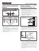
2. Position the electrical outlet within the space covered by the
decorative flue and where it will not interfere with the round
duct. Make sure the outlet is no further than 14” from where
the cord exits from the hood and that the outlet does not
interfere with a mounting bracket fastening area or where the
decorative flue touches the wall.
INSTALL THE WIRING
14”
MAX.
INSTALL THE HOOD MOUNTING
BRACKET
1. Construct wood wall framing that is flush with interior surface
of wall studs.
Make sure:
a) the framing is centered over installation location.
b) the height of the framing will allow the mounting bracket
to be secured to the framing within the dimensions
shown.
2. After wall surface is finished, carefully center and level the
hood mounting bracket and secure it to wall framing with (3)
#8 x 1-1/2” mounting screws. Tighten the screws completely.
NOTE:
On 8-ft. ceilings
Hood distance above cooktop is:
Minimum 30”, Maximum 32-3/4” (for ducted discharge)
Minimum 30”, Maximum 30” (for non-ducted discharge)
On 9-ft. ceilings
Hood distance above cooktop is:
Minimum 30”, Maximum 36” (for both ducted and non-ducted
discharge)
On 10-ft. ceilings
Hood distance above cooktop is:
Minimum 30”, Maximum 36” (for both ducted and non-ducted
discharge).
NOTE: 10-ft. ceilings require 10-ft. Flue Extension, Model
FXN58SS for ducted or non-ducted installations (purchase
separately).
7
7
⁄8”
42
5
⁄8” = bottom of hood 30” above cooktop
48
5
⁄8” = bottom of hood 36” above cooktop
3
15
⁄16”
FRAMING BEHIND
DRYWALL
1
9
⁄16”
WALL STUDS
42
5
⁄8” to 48
5
⁄8” above cooktop