RANGE HOOD Series: BCDA, BCS3, BCSM, NCDA, NCS3 and NCSEK INSTALLATION, USE AND CARE MANUAL Serial number: 99045652-101H
Safety . . . . . . . . . . . . . . . . . . . . . . . . . . . . . . . . . 3-4 Operation . . . . . . . . . . . . . . . . . . . . . . . . . . . . . . 5-6 Cleaning and Maintenance . . . . . . . . . . . . . . . . . 7 Motor Grease Filters Non-Ducted Recirculation Filters Fan Blade Stainless Steel Cleaning Painted Finish Cleaning Installation . . . . . . . . . . . . . . . . . . . . . . . . . . . . 8-22 INSTALLATION MANUAL TABLE OF CONTENTS Recommended Tools and Accessories for Installation . . . . . . . . . .
READ AND SAVE THESE INSTRUCTIONS ! Intended for domestic cooking only ! INSTALLER: LEAVE THIS MANUAL WITH HOMEOWNER. For Broan range hoods, register your range hood online at www.broan.ca For NuTone range hoods, register your range hood online at www.nutone.ca ! WARNING TO REDUCE THE RISK OF FIRE, ELECTRIC SHOCK, OR INJURY TO PERSONS, OBSERVE THE FOLLOWING: • Use this unit only in the manner intended by the manufacturer.
! WARNING TO REDUCE THE RISK OF A RANGE TOP GREASE FIRE: a) Never leave surface units unattended at high settings. Boilovers cause smoking and greasy spillovers that may ignite. Heat oils slowly on low or medium settings. b) Always turn hood ON when cooking at high heat or when flambeing food (i.e.: Crêpes Suzette, Cherries Jubilee, Peppercorn Beef Flambé). c) Clean ventilating fan frequently. Grease should not be allowed to accumulate on fan, filters or in exhaust ducts. d) Use proper pan size.
Operation Always turn your hood on before you begin cooking to establish an air flow in the kitchen. Let the blower run for a few minutes to clear the air after you turn off the range. This will help keep the whole kitchen cleaner and fresher. Operate the hood as follows: BCS3 AND NCS3 SERIES BLOWER SWITCH I • II Turns blower on to LOW speed. Turns blower OFF. Turns blower on to HIGH speed. LIGHT SWITCH I • II Turns light on to LOW intensity. Turns light OFF. Turns light on to HIGH intensity.
NCSEK SERIES BLOWER SWITCH I • II Turns blower on to LOW speed. Turns blower OFF. Turns blower on to HIGH speed. LIGHT SWITCH I • Turns light ON. Turns light OFF. The LED modules included with this hood are the latest in LED cooktop illumination technology specially designed to operate in the elevated temperatures of cooking - offering bright lighting and lasting up to 25 times as long as a standard bulb and greater reliability than typical replacement LED bulbs.
Cleaning and Maintenance Proper maintenance of the Range Hood will assure proper performance of the unit. MOTOR The motor is permanently lubricated and never needs oiling. If the motor bearings make excessive or unusual noise, replace the motor with the exact service motor. The fan blade should also be replaced. GREASE FILTERS The grease filters should be cleaned frequently. Use a warm dishwashing detergent solution. Clean all-metal filters using a non-phosphate detergent.
For ADA compliance installation guidelines, please type the model number into our website. Recommended Tools and Accessories for Installation • • • • • • • • • • • • • • • • Measuring tape Phillips screwdriver no.
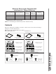
Maximum Duct Lengths Recommended to Achieve 80% Exhaust Efficiency 3¼” X 10” HORIZONTAL MAXIMUM DUCT LENGTH 3¼” X 10” VERTICAL MAXIMUM DUCT LENGTH 7” ROUND MAXIMUM DUCT LENGTH ROOF OR WALL CAP WITH DAMPER ELBOW(S)* (90° AND/OR 45°) 91 ft. 79 ft. 92 ft. 1 0 82 ft. 71 ft. 78 ft. 1 1 73 ft. 62 ft. 62 ft. 1 2 * Standard elbows with 1” internal radius. NOTE: 6" round ducting is possible but may reduce exhaust efficiency.
BCS3 and NCS3 Series BCSM Series (2) SHIELDED HALOGEN BULBS (50W, GU10) (2) GREASE FILTERS (FIND INSIDE OF HOOD) (2) GREASE FILTERS (1) 3¼” X 10” DAMPER ASSEMBLY (FIND INSIDE OF HOOD) (1) 3¼” X 10” DAMPER ASSEMBLY (FIND INSIDE OF HOOD) EZ1 COMPONENTS Use this template for marking; do not attempt to cut out the ducting hole through it. NOTE: These cutouts are clearance holes; they do not need to be the exact size of ducting.
Prepare the Hood NOTE: Since this manual covers many range hood models, some details in the following illustrations may sligthly differ from your unit. 1 ] If present, remove all protective polyfilm from the hood and/or parts. 2 ] Using the finger cup or tab, remove the grease filters from the hood by pushing down and tilting filter out . B C 3 ] Remove the EZ1 brackets from inside the hood by cutting off the tie wrap (no EZ1 brackets in BCS3 and NCS3 Series).
5 ] Remove 2 screws from top of hood (see illustration below). Keep the screws for further use. 2 SCREWS 6 ] Remove Electrical Power Cable Knockout from top (vertical wiring) or back (horizontal wiring) of hood. Install an appropriate strain relief, 1/2” diameter (not included). ELECTRICAL POWER CABLE KNOCKOUT NON-DUCTED INSTALLATION ONLY 7 ] Remove 3 screws retaining the recirculation cover plate (shaded part in illustration below) to the hood. Discard this plate with its screws.
DUCTED INSTALLATION ONLY 8 ] Remove 3¼” x 10” vertical, 3¼” x 10” horizontal, or 7-inch round knockout plate as appropriate for your ducting method (see FIGURES 1 A and 1 B).
Prepare the Hood Location NOTE: Before starting installation, read all the steps of these instructions. Use the illustration below to identify your kitchen cabinet type. FRAMED CABINET FRAMELESS CABINET This manual covers 2 kinds of installation: the standard (without EZ1 brackets) and the EZ1 one-person installation system (using included template and brackets). For the standard installation, go to page 19.
4 ] Drill a 1/8” dia. pilot hole for house wiring, at A location on template. 5 ] Use a sharp pencil or 1/8” drill bit to mark the locations for the appropriate duct access holes (16 locations for 7” round duct, or 4 corner locations for rectangular duct). Remove the template. 6 ] Draw the border for the exhaust ducting by linking its marks (16 for round duct and 4 for rectangular duct), then cut the opening in the cabinet bottom (vertical exhaust) or in the wall (horizontal exhaust).
FRAMELESS CABINET Refer to the marking on brackets to determine the correct installation side and orientation. X Y Z 3X [ \ INSTALLATION MANUAL INSTALLATION 7/64” 16 Align the corresponding bracket to the cabinet side, while placing rear end of bracket against the wall. Draw a line on the outer edge of the bracket (as shown). Slide the bracket towards the center of cabinet and align the outside edge of the bracket with the marked line, keeping the rear end edge leaning on the wall.
Install the Hood (EZ1 Brackets) NOTE: The following procedure applies to both framed or frameless cabinet installations. 1 ] Run house power cable between service panel and hood location. 2 ] There are 2 pairs of recessed holes on each side of the top of the hood (on rear: A and B, on front C and D on illustration below); these holes allow the range hood to hang on the brackets (previously installed).
7 ] For framed cabinet, secure the hood to the EZ1 brackets using 4 no. 8-18 x 1/2” metal screws (included in parts bag). Insert 2 screws per side, in the slots (as shown in insets on illustration below). 8 ] For frameless cabinet, secure the hood to the cabinet using 4 no. 8 x 5/8” round head wood screws (included in parts bag). Insert 2 screws per side, in the slots (as shown in insets on illustration below).
Standard Installation (without EZ1 brackets) 1 ] Use the proper diagram below for placement of ductwork and electrical cutout in cabinet or wall. For a non-ducted installation, DO NOT cut a duct access hole, only cut the hole for electrical wiring.
Install the Hood (Standard Installation) 1 ] Run house power cable between service panel and hood location. Run the house power cable into the hood through the strain relief previously installed in step 6 on page 12. 2 ] Hang hood from (4) mounting screws previously installed. Slide hood back towards wall until mounting screw heads are engaged in narrow end of keyhole slots in top of hood. Tighten screws securely. Attach power cable to the hood using the strain relief.
Connect the Wiring ! WARNING Risk of electric shock. Electrical wiring must be done by qualified personnel in accordance with all applicable codes and standards. Before connecting wires, switch power off at service panel and lock service disconnecting means to prevent power from being switched on accidentally. MOTOR GROUND WIRE GROUND SCREW HOUSE POWER CABLE 1 ] Connect House Power Cable to range hood wiring: BLACK to BLACK, WHITE to WHITE and GREEN or bare wire under GREEN ground screw.
Light Bulbs (BCS3, BCSM and NCS3 Series only) The BCS3, BCSM and NCS3 Series range hoods require two shielded Halogen Bulbs (120 V, 50 W max., MR16 or PAR16 with GU10 base) (included only with BCSM Series range hoods). ! WARNING Do not touch lamps during or soon after operation. Burns may occur. In order to prevent the risk of personal injury, only install shielded halogen lamps.
Ground Neutral Line INSTALLATION MANUAL BK BK G/Y Motor Switch WIRING DIAGRAM 120 V AC Light Switch BK BL BN BN/W BL W BK (High) R (Low) BLACK BLUE BROWN BROWN/WHITE W G/Y O R W COLOR CODE 2 1 BK W LED driver GREEN/YELLOW ORANGE RED WHITE R BK 1 2 R BK 6 5 4 3 2 1 W R O BK G/Y W FAN MOTOR LED LED BN/W BN NCSEK SERIES 23
120 V AC Ground Neutral Line User interface mounted to J10 on back of control board.
INSTALLATION MANUAL Ground Neutral Line WIRING DIAGRAM 120 V AC G/Y W BK W W BLACK BLUE BROWN W R (Low) O (Medium) BK (High) BL (High) Y (Low) 1 2 3 4 5 6 BK BL BN Motor On/Off 6 5 4 3 2 1 BN/W G/Y O 2 R FAN MOTOR BK BK W O BK G/Y 1 Motor Speeds BROWN/WHITE GREEN/YELLOW ORANGE COLOR CODE 3 BN/W BN R W Y Lights On/Off RED WHITE YELLOW Lights High/Low BCSM SERIES 25
Ground Neutral Line BK BK 2 1 Motor Switch 2 1 Light Switch WIRING DIAGRAM 120 V AC INSTALLATION MANUAL BK BL BN G/Y BLACK BLUE BROWN BL (High) W BK (High) R (Low) BROWN/WHITE GREEN/YELLOW ORANGE COLOR CODE Y (Low) BN/W G/Y O W W R W Y W RED WHITE YELLOW BK BK 6 5 4 3 2 1 R O BK G/Y W FAN MOTOR BN/W BN BCS3 AND NCS3 SERIES
NCSEK SERIES KEY NO. PART NO. S97020360 * S97020466 * * S99527587 S97020470 7 1 1 1 1 1 1 1 1 1 1 1 1 * ITEM NOT SHOWN. REPLACEMENT PARTS AND REPAIRS In order to ensure your unit remains in good working condition, you must use Venmar Ventilation ULC genuine replacement parts only.
BCDA AND NCDA SERIES QUANTITY INSTALLATION MANUAL SERVICE PARTS KEY NO. 28 30" 30" 30" 30" BLACK STAINLESS WHITE BLACK STAINLESS ** 1 S97020030 RECIRCULATION COVER PLATE, WHITE (INCLUDING SCREWS) S97020031 RECIRCULATION COVER PLATE, STAINLESS STEEL (INCLUDING SCREWS) 1 1 S97020029 RECIRCULATION COVER PLATE, BLACK (INCLUDING SCREWS) 1 S98011873 RECIRCULATION COVER PLATE, BLACK STAINLESS (INCL.
BCS3 SERIES KEY NO. 8 * S97020030 S97020031 S97020029 S97020534 S97020408 S97020407 SR99420635 S99010434-001 S99010434-002 S99030367 S99030355 S99030356 S97020448 S98011637 * S97018623 * S97020465 RECIRCULATION COVER PLATE, WHITE (INCLUDING SCREWS) RECIRCULATION COVER PLATE, STAINLESS STEEL (INCL.
NCS3 SERIES KEY NO.
BCSM SERIES KEY NO.
WARRANTY INSTALLATION MANUAL 32 Limited Warranty Warranty Period and Exclusions: Venmar Ventilation ULC (the “Company”) warrants to the original consumer purchaser of its product (“you”) that the product (the “Product”) will be free from material defects in the Product or its workmanship for a period of one (1) year from the date of original purchase (or such longer period as may be required by applicable law).
HOTTE DE CUISINIÈRE Séries : BCDA, BCS3, BCSM, NCDA, NCS3 et NCSEK MANUEL D’INSTALLATION, D’UTILISATION ET D’ENTRETIEN Numéro de série : 99045652-101H
Sécurité . . . . . . . . . . . . . . . . . . . . . . . . . . . . . . . 3-4 Fonctionnement . . . . . . . . . . . . . . . . . . . . . . . . . 5-6 Nettoyage et entretien . . . . . . . . . . . . . . . . . . . . . 7 Moteur Filtres à graisses Filtres de recirculation Hélice Nettoyage de l’acier inoxydable Nettoyage des surfaces peintes INSTALLATION MANUEL D’INSTALLATION MANUAL WARRANTY TABLE DES MATIÈRES Installation . . . . . . . . . . . . . . . . . . . . . . . . . . . .
VEUILLEZ LIRE ET CONSERVER CES DIRECTIVES ! Conçues pour usage domestique seulement ! INSTALLATEUR : LAISSER CE MANUEL AU PROPRIÉTAIRE. Pour une hotte Broan, enregistrez votre hotte en ligne à www.broan.ca Pour une hotte NuTone, enregistrez votre hotte en ligne à www.nutone.ca ! AVERTISSEMENT AFIN DE RÉDUIRE LES RISQUES D’INCENDIE, D’ÉLECTROCUTION OU DE BLESSURES CORPORELLES, SUIVEZ LES DIRECTIVES SUIVANTES : • N’utilisez cet appareil que de la façon prévue par le manufacturier.
! AVERTISSEMENT AFIN DE RÉDUIRE LES RISQUES DE FEU DE CUISINIÈRE : a) b) c) d) Ne jamais laisser les appareils de cuisson sans surveillance lorsqu’ils sont réglés à feu vif. Les débordements engendrent de la fumée et des déversements graisseux pouvant s’enflammer. Chauffez l’huile lentement, à feu doux ou moyen. Mettez toujours la hotte en marche lorsque vous cuisinez à feu vif ou que vous cuisinez des mets flambés (par ex. : crêpes Suzette, cerises jubilé, steaks au poivre flambés).
Fonctionnement Toujours mettre en marche la hotte avant de commencer la cuisson afin d’établir une circulation d’air dans la cuisine. Laisser également la hotte fonctionner quelques minutes après l’arrêt de la cuisinière afin de nettoyer l’air. Cela aidera à maintenir la cuisine plus propre et plus fraîche. Faire fonctionner la hotte comme suit : SÉRIES BCS3 ET NCS3 COMMUTATEUR DE L’ÉCLAIRAGE COMMUTATEUR DU VENTILATEUR I • II Active le ventilateur à BASSE vitesse. ARRÊTE le ventilateur.
SÉRIE NCSEK COMMUTATEUR DU VENTILATEUR I • II Active le ventilateur à BASSE vitesse. ARRÊTE le ventilateur. Active le ventilateur à vitesse ÉLEVÉE. COMMUTATEUR DE L’ÉCLAIRAGE I • Allume les lumières. ÉTEINT les lumières. Cette hotte est munie de modules DEL offrant un éclairage brillant, issus de la plus récente technologie en matière d’éclairage de surface de cuisson et spécialement conçus pour fonctionner dans un environnement à chaleur élevée.
Nettoyage et entretien L’entretien adéquat de la hotte préservera ses performances. MOTEUR Le moteur est lubrifié en permanence et n’a pas besoin d’être huilé. Si les roulements du moteur sont anormalement bruyants, remplacer le moteur uniquement par le même modèle. L’hélice doit aussi être remplacée. FILTRES À GRAISSES Les filtres à graisses doivent être nettoyés fréquemment. Utiliser une solution d’eau chaude et de détergent.
Pour connaître les lignes directrices de l’ADA (Americans with Disabilities Act) concernant l’installation, veuillez entrer votre numéro de modèle dans notre site Internet.
Longueurs maximales de conduit recommandées pour obtenir une efficacité d’évacuation de 80% LONGUEUR MAXIMALE LONGUEUR MAXIMALE LONGUEUR DE CONDUIT DE CONDUIT MAXIMALE DE DE MUR OU CONDUIT DE DE TOIT AVEC 3¼ PO X 10 PO, DE DE 3¼ PO X 10 PO, CAPUCHON COUDE(S)* DE (90° ET/OU 45°) HORIZONTAL VERTICAL 7 PO ROND CLAPET 91 pi 79 pi 92 pi 1 0 82 pi 71 pi 78 pi 1 1 73 pi 62 pi 62 pi 1 2 * Coudes standards de rayon interne de 1 po.
Séries BCS3 et NCS3 Série BCSM (2) AMPOULES HALOGÈNES (50W, GU10) AVEC ÉCRAN (2) FILTRES À GRAISSES (À L’INTÉRIEUR DE LA HOTTE) (2) FILTRES À GRAISSES (1) ADAPTATEUR/VOLET 3¼ PO X 10 PO (À L’INTÉRIEUR DE LA HOTTE) (1) ADAPTATEUR/VOLET 3¼ PO X 10 PO (À L’INTÉRIEUR DE LA HOTTE) COMPOSANTS EZ1 Use this template for marking; do not attempt to cut out the ducting hole through it. NOTE: These cutouts are clearance holes; they do not need to be the exact size of ducting.
Préparation de la hotte NOTE : Puisque ce manuel couvre plusieurs modèles de hottes de cuisinière, certains détails de votre hotte peuvent être légèrement différents de ceux illustrés. 1 ] Retirer toute présence de pellicule de plastique protectrice sur la hotte et/ou ses pièces. 2 ] Enlever les filtres à graisses en insérant un doigt dans la prise concave de chaque filtre à graisses ou en tirant sur la languette, puis en poussant vers l’arrière de la hotte et en les basculant .
5 ] Retirer les deux vis du dessus de la hotte (voir l’illustration ci-dessous). Garder les vis pour usage ultérieur. 2 VIS 6 ] Retirer l’ouverture préamorcée du câble d’alimentation électrique du dessus (câblage vertical) ou de l’arrière de la hotte (câblage horizontal). Installer un serre-fils approprié de 1/2 po de diamètre (non inclus).
INSTALLATION AVEC CONDUITS SEULEMENT 8 ] Retirer les ouvertures préamorcées de 3¼ po x 10 po verticale, 3¼ po x 10 po horizontale, ou 7 po ronde selon le mode d’évacuation choisi (voir les FIGURES 1 A et 1 B).
Préparation de l’emplacement de la hotte NOTE : Avant de commencer l’installation, veuillez lire toutes les étapes de cette instruction. Identifier votre type d’armoire de cuisine à l’aide de l’illustration ci-dessous. ARMOIRE À FOND EN RETRAIT ARMOIRE À FOND ÉGAL Ce manuel couvre deux types d’installation : l’installation standard (sans les supports EZ1) et le système d’installation par une personne EZ1 (en utilisant le gabarit et les supports inclus). Pour l’installation standard, allez en page 19.
4 ] Percer un avant-trou de 1/8 po de diamètre pour le câble d’alimentation, à l’emplacement A sur le gabarit. 5 ] Utiliser un crayon pointu ou un foret de 1/8 po pour marquer les repères du trou pour le conduit approprié (16 endroits pour le conduit rond de 7 po, ou aux 4 coins pour les conduits rectangulaires). Retirer le gabarit.
ARMOIRE À FOND ÉGAL Voir les inscriptions sur les supports pour les installer dans le bon sens (inscriptions en anglais seulement : front = avant, left = gauche, lean on rear wall = appuyer sur le mur arrière). X Y Z 3X [ \ MANUEL D’INSTALLATION INSTALLATION 7/64 po 16 Aligner le support correspondant au côté de l’armoire, tout en appuyant l’extrémité arrière du support contre le mur. Tracer une ligne le long du rebord externe du support (tel qu’il est illustré).
Installation de la hotte (avec supports EZ1) NOTE : La procédure convient autant pour les armoires à fond en retrait qu’à fond égal. 1 ] Acheminer le câble d’alimentation depuis le panneau de distribution de la maison jusqu’à l’emplacement de la hotte. 2 ] De chaque côté de la hotte, sur le dessus, se trouvent 2 paires de trous enfoncés (à l’arrière : A et B, à l’avant : C et D dans l’illustration ci-dessous); ces trous permettent à la hotte de s’accrocher aux supports (installés précédemment).
7 ] Pour une armoire à fond en retrait, fixer la hotte au supports EZ1 à l’aide de 4 vis à métaux n° 8-18 x 1/2 po (vis incluses dans le sac de pièces). Insérer 2 vis par côté, dans les fentes (tel qu’il est démontré dans les médaillons de l’illustration ci-dessous). 8 ] Pour une armoire à fond égal, fixer la hotte à l’armoire à l’aide de 4 vis à bois à tête ronde n° 8 x 5/8 po (vis incluses dans le sac de pièces).
Installation standard (sans supports EZ1) 1 ] Utiliser le diagramme approprié ci-dessous pour déterminer l’emplacement exact des coupes à effectuer pour le conduit et le fil d’alimentation électrique dans l’armoire ou le mur. Pour une installation en recirculation, NE PAS découper un trou pour le conduit.
Installation de la hotte (installation standard) 1 ] Acheminer le câble d’alimentation électrique du panneau de distribution jusqu’à l’emplacement de la hotte. Insérer le cable d’alimentation dans la hotte à travers le serre-fils installé précédemment à l’étape 6 en page 12. 2 ] Suspendre a hotte à l’aide des (4) vis de montage installées précédemment. Glissez la hotte vers le mur de manière à engager la tête des vis dans la partie étroite des trous en forme de serrure du dessus de la hotte.
Branchement électrique ! AVERTISSEMENT Risque d’électrocution. Le raccordement électrique doit être effectué par du personnel qualifié conformément aux codes et aux standards en vigueur. Avant d’effectuer le branchement, coupez l’alimentation électrique au panneau de distribution et verrouillez-le pour éviter une mise en marche accidentelle.
Ampoules (Séries BCS3, BCSM et NCS3 seulement) L’éclairage de hottes des séries BCS3, BCSM et NCS3 est produit par deux ampoules halogènes avec écran (120 V, 50 W max., MR16 ou PAR16 à culot GU10) (incluses seulement avec les hottes de série BCSM). ! AVERTISSEMENT Ne pas toucher aux lampes durant ou peu après leur utilisation. Peuvent causer des brûlures. Afin de réduire le risque de blessures corporelles, n’installer que des ampoules halogènes avec écran.
Mise à la terre Neutre Ligne N MANUEL D’INSTALLATION N V/J Commutateur du moteur Commutateur d’éclairage SCHÉMA ÉLECTRIQUE 120 V CA BLA BLE BR BR/BLA BLE BLA N (Haute) R (Basse) BLA N O R V/J 2 1 N BLA NOIR ORANG ROUGE VERT/JAUNE CODE DES COULEURS BLANC BLEU BRUN BRUN/BLANC Module d’alimentation DEL R N 1 2 R N 6 5 4 3 2 1 BLA R O N V/J BLA MOTEUR DU VENTILATEUR DEL DEL BR/BLA BR SÉRIE NCSEK 23
120 V CA Mise à la terre Neutre Ligne Interface de l’utilisateur connectée à J10 à l’arrière de la carte électronique J10 8 7 6 5 4 3 2 1 BLA N Carte électronique Interface Commande prioritaire J6 1 2 3 4 5 6 DEL 7 6 5 4 3 2 1 5 4 3 2 1 1 2 3 4 N N BLE BLA BLE BR BR/BLA BLE SCHÉMA ÉLECTRIQUE J4 J1 J2 24 Alimentation, Moteur Transformateur MANUEL D’INSTALLATION R R BLA V/J R N O (Moyenne) N O R V/J BLA N (Haute) BLA NOIR ORANGE ROUGE VERT/JAUNE R (Basse) CODE DES COULE
MANUEL D’INSTALLATION BLA V/J Neutre Mise à la terre Ligne N SCHÉMA ÉLECTRIQUE 120 V CA 5 6 1 2 3 4 BLA BLA 6 5 4 3 2 1 N 1 BR/BLA J N BLA V/J O MOTEUR DU VENTILATEUR R N N 2 BR 3 O R V/J BR/BLA Vitesses du moteur BRUN/BLANC JAUNE NOIR CODE DES COULEURS Moteur Marche/Arrêt BLANC BLEU BRUN BLA R (Basse) O (Moyene) N (Haute) BL (Haute) J (Basse) BLA BLE BR Éclairage Allumé/ Éteint ORANGE ROUGE VERT/JAUNE Intensité d’éclairage Haute/Basse SÉRIE BCSM 25
26 Mise à la terre Neutre Ligne N N 2 1 Commutateur du moteur 2 1 Commutateur d’éclairage BLA BLE BR V/J BLANC BLEU BRUN SCHÉMA ÉLECTRIQUE 120 V CA MANUEL D’INSTALLATION BRUN/BLANC JAUNE NOIR BLA N (Haute) R (Basse) BLE (Haute) J (Basse) BR/BLA J N CODE DES COULEURS BLA O R V/J BLA BLA ORANGE ROUGE VERT/JAUNE N N 6 5 4 3 2 1 R O N V/J BLA MOTEUR DU VENTILATEUR BR/BLA BR SÉRIES BCS3 ET NCS3
SÉRIE NCSEK REPÈRE Nº DE PIÈCE S97020379 * S97020466 * * S99527587 S97020470 7 1 1 1 1 1 1 1 1 1 1 1 1 * ARTICLE NON ILLUSTRÉ. PIÈCE DE REMPLACEMENT ET SERVICE Pour assurer le bon fonctionnement de votre appareil, vous devez toujours utiliser des pièces d’origine provenant de Venmar Ventilation ULC. Les pièces d’origine de Venmar Ventilation ULC sont spécialement conçues pour satisfaire toutes les normes de certification de sécurité applicables.
SÉRIES BCDA ET NCDA REPÈRE MANUEL D’INSTALLATION PIÈCES DE RECHANGE 1 28 2 3 4 5 6 7 8 9 * * * * * * QUANTITÉ 30 PO 30 PO 30 PO 30 PO INOX BLANCHE NOIRE INOX NOIRE** S97020030 PLAQUE DE GRILLE DE RECIRCULATION, BLANCHE (INCL. LES VIS) 1 S97020031 PLAQUE DE GRILLE DE RECIRCULATION, INOX (INCLUANT LES VIS) 1 S97020029 PLAQUE DE GRILLE DE RECIRCULATION, NOIRE (INCLUANT LES VIS) 1 S98011873 PLAQUE DE GRILLE DE RECIRCULATION, INOX. NOIR (INCL.
SÉRIE BCS3 REPÈRE 1 2 3 4 5 7 8 * * * * * QUANTITÉ 24 PO 24 PO 30 PO 30 PO 30 PO INOX. BLANCHE INOX. BLANCHE NOIRE 1 1 S97020030 PLAQUE DE GRILLE DE RECIRCULATION, BLANCHE (INCL. LES VIS) S97020031 PLAQUE DE GRILLE DE RECIRCULATION, INOX. (INCLUANT LES VIS) 1 1 S97020029 PLAQUE DE GRILLE DE RECIRCULATION, NOIRE (INCLUANT LES VIS) 1 S97020534 ADAPTATEUR/VOLET DE 3¼ PO X 10 PO (INCLUANT LES VIS) 1 1 1 1 1 S97020408 MOTEUR DU VENTILATEUR (INCL.
SÉRIE NCS3 REPÈRE PIÈCES DE RECHANGE MANUEL D’INSTALLATION 30 Nº DE PIÈCE 8 * S97020030 S97020031 S97020029 S97020534 S97020408 S97020407 SR99420635 S99010434-002 S99030367 S99030355 S99030356 S97020448 S98011637 * S97018623 * S97020466 * * S99527587 SV05921 1 2 3 4 5 6 7 DESCRIPTION PLAQUE DE GRILLE DE RECIRCULATION, BLANCHE (INCLUANT LES VIS) PLAQUE DE GRILLE DE RECIRCULATION, INOX.
SÉRIE BCSM REPÈRE Nº DE PIÈCE S97020292 * S97020466 * * * S99527587 SV05921 S97020470 DESCRIPTION PLAQUE DE GRILLE DE RECIRCULATION, BLANCHE (INCLUANT LES VIS) PLAQUE DE GRILLE DE RECIRCULATION, INOX.
GARANTIE MANUEL D’INSTALLATION 32 Garantie limitée Période de garantie et exclusions : Venmar Ventilation ULC (la « Société ») garantit au consommateur acheteur initial (« vous ») de son produit (le « Produit ») que celui-ci est exempt de tout vice de matériau ou de fabrication pour une période de un (1) an à compter de la date d’achat originale (ou toute période plus longue que pourrait exiger une loi applicable).