WWW.BROAN-NUTONE.COM WWW.BROAN.CA WWW.NUTONE.
Safety . . . . . . . . . . . . . . . . . . . . . . . . . . . . . . . . . 3-4 Operation . . . . . . . . . . . . . . . . . . . . . . . . . . . . . . 5-6 Cleaning and Maintenance . . . . . . . . . . . . . . . . . 7 Motors Grease Filters Non-Ducted Recirculation Filters Fan Wheels Stainless Steel Cleaning Painted Finish Cleaning Installation . . . . . . . . . . . . . . . . . . . . . . . . . . . . 8-21 INSTALLATION MANUAL TABLE OF CONTENTS Recommended Tools and Accessories for Installation . . . . . . . . .
READ AND SAVE THESE INSTRUCTIONS ! Intended for domestic cooking only ! INSTALLER: LEAVE THIS MANUAL WITH HOMEOWNER. In U.S.A., register your Broan range hood online at www.broan-nutone.com. In Canada, register your Broan range hood online at www.broan.ca or register your NuTone range hood online at www.nutone.ca ! WARNING TO REDUCE THE RISK OF FIRE, ELECTRIC SHOCK, OR INJURY TO PERSONS, OBSERVE THE FOLLOWING: • Use this unit only in the manner intended by the manufacturer.
! WARNING TO REDUCE THE RISK OF A RANGE TOP GREASE FIRE: a) Never leave surface units unattended at high settings. Boilovers cause smoking and greasy spillovers that may ignite. Heat oils slowly on low or medium settings. b) Always turn hood ON when cooking at high heat or when flambeing food (i.e.: Crêpes Suzette, Cherries Jubilee, Peppercorn Beef Flambé). c) Clean ventilating fan frequently. Grease should not be allowed to accumulate on fan, filters or in exhaust ducts. d) Use proper pan size.
Operation Always turn your hood on before you begin cooking to establish an air flow in the kitchen. Let the blower run for a few minutes to clear the air after you turn off the range. This will help keep the whole kitchen cleaner and fresher. This hood is equipped with infrared sensing controls. To activate it, simply touch the sensor corresponding to the desired function and/or intensity. At the touch of the sensor, a beep is emitted to acknowledge the command.
LIGHTING/LIGHT INTENSITY CHANGE To turn the lighting ON, touch the sensor corresponding to the desired lighting intensity and the sensor will illuminate. When the lighting is ON, touch the sensor corresponding to the active light intensity to turn the lighting OFF and memorize the intensity.
Cleaning and Maintenance Proper maintenance of the Range Hood will assure proper performance of the unit. MOTORS The motors are permanently lubricated and never need oiling. If the motor bearings make excessive or unusual noise, replace the motor with the exact service motor. The fan wheel should also be replaced. GREASE FILTERS The grease filters should be cleaned frequently. Use a warm dishwashing detergent solution. Grease filters are diswasher safe.
For ADA compliance installation guidelines, please type the model number into our website. Recommended Tools and Accessories for Installation • • • • • • • • • • • • • • • • • Measuring tape Phillips screwdriver no.
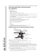
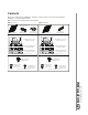
Contents Before proceeding to the installation, check the contents of the box. If items are missing or damaged, contact the manufacturer. Make sure that the following items are included: BQLA1 Series NQLA1 Series * FIND INSIDE ONE PACKAGING STYROFOAM OF HOOD (1) 7” ROUND DUCT CONNECTOR (1) 3¼” X 10” DAMPER ASSEMBLY* (2) GREASE FILTERS EZ1 COMPONENTS Use this template for marking; do not attempt to cut out the ducting hole through it.
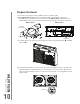
Prepare the Hood 1 ] If present, remove all protective polyfilm from the hood and/or parts. 2 ] For BQLA1 Series only: Remove 7” Round Duct Plate from top/back of hood (see illustration below). Keep the screws for further use. For NQLA1 Series only: Remove the adapter/damper from back of hood (see illustration below). Keep the screws for further use.
5 ] Remove the parts bag, taped on the inner back of hood, near the left corner. Remove the EZ1 brackets from inside the hood by cutting off the tie wrap. Discard the tie wrap. EZ1 BRACKETS PARTS BAG LOCATION 6 ] Remove Electrical Power Cable Knockout from top (vertical exhaust) or back (horizontal exhaust) of hood. For knockout removed from back of hood, install an appropriate strain relief, 1/2” diameter (not included). For knockout removed from top of hood, the strain relief will be installed later.
DUCTED INSTALLATION ONLY 8 ] Remove 3¼” x 10” vertical, 3¼” x 10” horizontal (both are the rectangular central knockout plates, see hatched areas) or 7-inch round knockout plate as appropriate for your ducting method (see FIGURES 1 A and 1 B).
Prepare the Hood Location NOTE: Before starting installation, read all the steps of these instructions. Use the illustration below to identify your kitchen cabinet type. FRAMED CABINET FRAMELESS CABINET This manual covers 2 kinds of installation: the standard (without EZ1 brackets) and the EZ1 one-person installation system (using included template and brackets). For the standard installation, go to page 18.
4 ] Drill a 1/8” dia. pilot hole for house wiring, at B location on template. 5 ] Use a sharp pencil or 1/8” drill bit to mark the locations for the appropriate duct access holes (16 locations for 7” round duct, or 4 corner locations for rectangular duct). Remove the template. 6 ] Draw the border for the exhaust ducting by linking its marks (16 for round duct and 4 for rectangular duct), then cut the opening in the cabinet bottom (vertical exhaust) or in the wall (horizontal exhaust).
FRAMELESS CABINET Refer to the marking on brackets to determine the correct installation side and orientation. X Y Z 3X [ \ 7/64” against the wall. Draw a line on the outer edge of the bracket (as shown). marked line, keeping the rear end edge leaning on the wall. Use a pencil to mark 3 holes. Remove the bracket. Using a 7/64” drill bit, drill 3 holes where marked. Assemble the bracket to the cabinet bottom using a Phillips screwdriver and 3 provided countersunk wood screws.
Install the Hood (EZ1 Bracket) NOTE: The following procedure applies to both frame or frameless cabinet installations. 1 ] Run house power cable between service panel and hood location. 2 ] There are 2 pairs of recessed holes on each side of the top of the hood (on rear: A and B, on front C and D on illustration below); these holes allow the range hood to hang on the brackets (previously installed).
7 ] For framed cabinet, secure the hood to the EZ1 brackets using four (4) no. 8-18 x 1/2” metal screws (included in parts bag). Insert two (2) screws per side, in the slots (as shown in insets on illustration below). 8 ] For frameless cabinet, secure the hood to the cabinet using four (4) no. 8 x 5/8” round head wood screws (included in parts bag). Insert two (2) screws per side, in the slots (as shown in insets on illustration below).
Standard Installation (without EZ1 brackets) 1 ] Use the proper diagram below for placement of ductwork and electrical cutout in cabinet or wall. For a non-ducted installation, DO NOT cut a duct access hole, only cut the hole for electrical wiring.
Install the Hood (Standard Installation) NOTE: Two installers are recommended because of the weight of this hood. 1 ] Run house power cable between service panel and hood location. For hood with power cable access located on back of hood, run the house power cable into the hood through the strain relief previously installed in step 6 on page 11. For hood with power cable access located on top, tighten the strain relief to the power cable before inserting the strain relief in the knockout hole.
Connect the Wiring ! WARNING Risk of electric shock. Electrical wiring must be done by qualified personnel in accordance with all applicable codes and standards. Before connecting wires, switch power off at service panel and lock service disconnecting means to prevent power from being switched on accidentally. MOTORS GROUND WIRE GROUND SCREW HOUSE POWER CABLE 1 ] Connect House Power Cable to range hood wiring: BLACK to BLACK, WHITE to WHITE and GREEN or bare wire under GREEN ground screw.
BQLA1 SERIES (SECOND GENERATION) BK R RF Communication 1 2 3 4 5 4 J8 1 3 2 J4 ADA RF User Interface ADA Override LED BK Ground G/Y BK BL BN BN/W G/Y 2 4 5 6 7 8 9 10 R GRY GRY User interface 1 12 CN3 3 42 BLACK BLUE BROWN BROWN/WHITE GREEN/YELLOW GRY O R W GREY ORANGE RED WHITE Ref: 990729482A GRY Transformer BL BL 1 2 3 24 V Class 2 4 5 BN FAN MOTOR R 6 5 4 3 2 1 R (L) O (M) BK (H) G/Y W R R J1 O BK G/Y BK C M BK W 1 2 3 Power, Motor Line Neutral 1 COLOR CO
BQLA1 SERIES C First Generation: Serial number 091810008492 and previous. B D E M N O L G F K H I J KEY NO. PART NO.
BQLA1 SERIES C Second Generation: Serial number 091810008493 and up. B N D L E M K F J G H I KEY NO.
NQLA1 SERIES First Generation: Serial number 091810008492 and previous. B C M L D K F E J G H I KEY NO.
NQLA1 SERIES Second Generation: Serial number 091810008493 and up. B C D L K J E I F G H KEY NO. 2 3 4 5 6 7 8 9 10 11 * S97020030 S97020031 S97020534 S97020412 S97021326 SR99420635 S97021339 S97020204-002 S97021327 S97021392 S97020444 S97020441 S97020454 * S97020360 * S97020466 * * S99527587 S97020470 RECIRCULATION COVER PLATE, WHITE (INCLUDING SCREWS) RECIRCULATION COVER PLATE, STAINLESS STEEL (INCL.
WARRANTY INSTALLATION MANUAL 26 Limited Warranty Warranty Period and Exclusions: Broan-NuTone LLC and Venmar Ventilation ULC (either being the “Company”) warrants to the original consumer purchaser of its product (“you”) that the product (the “Product”) will be free from material defects in the Product orits workmanship for a period of one (1) year from the date of original purchase (or such longer period as may be required by applicable law).