INSTALLATION INSTRUCTIONS HB0040 MODEL E661 HB0037 ! INTENDED FOR DOMESTIC COOKING ONLY ! READ AND SAVE THESE INSTRUCTIONS INSTALLER: LEAVE THIS MANUAL WITH HOMEOWNER. HOMEOWNER: USE AND CARE INFORMATION ON PAGES 7 AND 8. Broan-NuTone LLC; Hartford, Wisconsin www.broan.com 800-558-1711 Broan-NuTone Canada; Mississauga, Ontario www.broan.ca 877-896-1119 REGISTER YOUR PRODUCT ON LINE AT: www.broan.com/register SV06112 rev.
! WARNING ! WARNING TO REDUCE THE RISK OF FIRE, ELECTRIC SHOCK OR INJURY TO PERSONS, OBSERVE THE FOLLOWING: TO REDUCE THE RISK OF INJURY TO PERSONS IN THE EVENT OF A RANGE TOP GREASE FIRE, OBSERVE THE FOLLOWING*: 1. Use this unit only in the manner intended by the manufacturer. If you have questions, contact the manufacturer at the address or telephone number listed in the warranty.
TABLE OF CONTENTS 1. INSTALL DUCTWORK . . . . . . . . . . . . . . . . . . . . . . . . . . . . . . . . . . . . . . . . . . . . . . . . . . . . . . . . . . .4 2. PREPARE THE INSTALLATION . . . . . . . . . . . . . . . . . . . . . . . . . . . . . . . . . . . . . . . . . . . . . . . . . . . . . . .4-5 3. PREPARE THE HOOD . . . . . . . . . . . . . . . . . . . . . . . . . . . . . . . . . . . . . . . . . . . . . . . . . . . . . . . . . . .5-6 4. INSTALL THE ADAPTER/DAMPER . . . . . . . . . . . . . . . . . . . . . .
1. INSTALL DUCTWORK Plan where and how the ductwork will be installed. Install proper-sized ductwork, elbows and roof or wall cap. Use 2” duct tape to seal duct joints. The minimum hood distance above cooktop must not be less than 24”. A maximum of 30” above cooktop is highly recommended for best capture of cooking impurities. Distances over 30” are at the installer and users discretion.
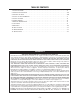
2. PREPARE THE INSTALLATION (CONT’D) Cut-out the openings for duct (A) and power cable (B), in cabinet or wall, according to the direction of discharge chosen. See figures below. NOTE: If using the optional adaptor 3¼” x 14” to 3¼” x 10” model no. T461, the duct opening width (A on figures below) will be 10½”, centered. HORIZONTAL VERTICAL DISCHARGE DISCHARGE CABINET BOTTOM C L 1½’’ A C L 1³ 8’’ 4¼’’ A 7¼’’ 3½” 7 8” 7¼” HD0121A HD0120A 7¼” 7¼’’ B 2’’ 2’’ 7/8’’ B 2¾” 1½” dia. 3.
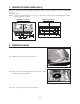
3. PREPARE THE HOOD (CONT’D) FOR VERTICAL DISCHARGE ONLY: The hood is set up at the factory for vertical discharge. Go to step 4 on page 7. Start on step 4.4. FOR HORIZONTAL DISCHARGE ONLY: 3.4 From inside the hood, unfold the small retaining tab (A) (located on the edge of the blower opening) on the air diffuser edge. See pictures below. A A HD0109 HD0108 Folded tab Unfolded tab 3.5 Remove the metal shutoff plate from the back of the hood, by removing the 3 screws. Set aside scews. HO0031 3.
4. INSTALL THE ADAPTER/DAMPER The wall duct must be roughed-in to properly interface with the hood. Before performing the installation, make sure the adapter fits easily in the duct. If this hood replaces an existing hood, please note that location of the air exhaust can vary from one hood manufacturer to another. NOTE: If using the optional adaptor 3¼” x 14” to 3¼” x 10” model T461, discard the provided adapter/damper and perform step 4 with the optional adaptor T461. FOR HORIZONTAL DISCHARGE ONLY: 4.
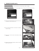
5. INSTALL THE HOOD 5.1 Run power cable to installation location. Position the hood in its intended location. Using a pen, mark the position ! of the screws (smaller part of the keyholes, see pictures below for the (5) keyholes locations). Remove the hood. 5.2 Install (4) no. 8 x 1/2’’ screws, leaving a 1⁄8’’ gap (do not install the no. 5 screw yet). 3 1 5 1 3 4 2 2 4 HD0122 HD0123 HD0115 5.
7. REINSTALL BOTTOM PANEL Reinstall the bottom panel, using 5 screws saved from step 3, as shown beside. Reinstall filters. CAUTION Remove protective plastic film covering filters before installing them. HD0124 8. LIGHT BULBS This hood must use 120 V, 50 W max., type MR16, GU10 shielded halogen lamps. (Purchase separately). ! WARNING In order to prevent the risk of personal injury, do not install a lamp identified for use only in enclosed fixtures.
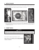
9. OPERATION Always turn your blower on before you begin cooking to establish an air flow in the kitchen. Let the blower run for a few minutes to clear the air after you turn off the range. HC0016 A B C D E A) Blower Delay switch B) ON blower/Speed control switch C) OFF blower/Filter maintenance switch D) OFF lighting E) Halogen light switch A. BLOWER DELAY SWITCH: When a speed is selected, press the delay switch to activate the delay function.
10. USE AND CARE Grease filters and bottom panel. The grease filters and the bottom panel should be cleaned frequently. Use a warm detergent solution. Remove grease filters by pushing them towards the back of hood and rotating downward. Clean all-metal filters in the diswasher using a non-phophate detergent. Discoloration of the filter may occur if using phosphate detergents, or as a result of local water conditions — but this will not affect filter performance.
. SERVICE PARTS E661 MODEL 1 2 11 13 3 9 8 10 12 4 5 6 6 7 HL0052 KEY NO. PART NO. 1 2 3 4 5 6 * SV14971 SV06118 SV05917 SV06735 SV01766E SV06268 SV06244 SV06264 SV02160 SV06750 SV06733-1 SV06252 SV05921 SV03443 SV06734 SV06745 SV06746 SV06112 * SV06751 7 8 9 10 11 12 13 * DESCRIPTION ADAPTER/DAMPER ELECTRONIC CONTROL LAMP SOCKET TRANSFORMER AND HARNESS KIT MOTOR (INCLUDING WHEEL) LIGHT TRIM RING FILTERS 9.92” x 17.981” FILTERS 12.922” x 17.
GUIDE D’INSTALLATION HB0040 MODÈLE E661 HB0037 ! CONÇUE POUR USAGE DOMESTIQUE SEULEMENT ! LIRE ET CONSERVER CES DIRECTIVES INSTALLATEUR : LAISSER CE GUIDE AU PROPRIÉTAIRE. PROPRIÉTAIRE : DIRECTIVES D’UTILISATION ET D’ENTRETIEN AUX PAGES 22-23. Broan-NuTone LLC; Hartford, Wisconsin www.broan.com 800 558-1711 Broan-NuTone Canada; Mississauga, Ontario www.broan.ca 877 896-1119 ENREGISTREZ VOTRE PRODUIT EN LIGNE À : www.broan.com/register SV06112 rév.
! AVERTISSEMENT ! AFIN DE DIMINUER LE RISQUE D’INCENDIE, D’ÉLECTROCUTION OU DE BLESSURES, SUIVEZ LES DIRECTIVES SUIVANTES : 1. N’utilisez cet appareil que de la façon prévue par le manufacturier. Si vous avez des questions, contactez ce dernier à l’adresse et au numéro de téléphone indiqués sur la garantie. 2. Avant de réparer ou de nettoyer l’appareil, coupez le courant au panneau d’alimentation et verrouillezen l’accès afin d’éviter sa remise en marche accidentelle.
TABLE DES MATIÈRES 1. INSTALLATION DES CONDUITS . . . . . . . . . . . . . . . . . . . . . . . . . . . . . . . . . . . . . . . . . . . . . . . . . . . .16 2. PRÉPARATION DE L’INSTALLATION . . . . . . . . . . . . . . . . . . . . . . . . . . . . . . . . . . . . . . . . . . . . . . . . . .16-17 3. PRÉPARATION DE LA HOTTE . . . . . . . . . . . . . . . . . . . . . . . . . . . . . . . . . . . . . . . . . . . . . . . . . . . . .17-18 4. INSTALLATION DE L’ADAPTATEUR/VOLET . . . . . . . . . . . . . . . . . . . . . .
1. INSTALLATION DES CONDUITS Planifier à quel endroit et de quelle façon les conduits seront installés. Installer des conduits de format adéquat, coude(s) et capuchon de mur ou de toit. Sceller les joints avec du ruban adhésif en toile de 2 po de largeur. La distance minimale entre le bas de votre hotte et la surface de cuisson ne doit pas être inférieure à 24 po. Un maximum de 30 po au dessus de la surface de cuisson est fortement recommandé pour une meilleure évacuation des odeurs de cuisson.
2. PRÉPARATION DE L’INSTALLATION (SUITE) Découper, dans l’armoire ou le mur, les ouvertures pour le conduit (A) et le fil d’alimentation électrique (B), selon ! l’évacuation choisie (horizontale ou verticale). Voir les illustrations ci-dessous. NOTE : Si l’adaptateur optionnel de 3¼ po x 14 po à 3¼ po x 10 po (modèle T461) sera utilisé, la largeur de l’ouverture du conduit (A dans les illustrations ci-dessous) sera de 10½ po, centrée.
3. PRÉPARATION DE LA HOTTE (SUITE) INSTALLATION AVEC SORTIE VERTICALE SEULEMENT : La hotte est prémontée en usine pour une évacuation verticale. Aller à l’étape 4 en page 19. Commencer au point 4.4. INSTALLATION AVEC SORTIE HORIZONTALE SEULEMENT : 3.4 Par l’intérieur de la hotte, déplier la languette de retenue (A) (située sur le bord de l’ouverture pour le ventilateur) sur le bord du diffuseur. Voir les photos ci-dessous. A A HD0109 HD0108 Languette pliée Languette dépliée 3.
4. INSTALLATION DE L’ADAPTATEUR/VOLET Le conduit doit être bien préparé pour recevoir l’adaptateur. Avant d’installer la hotte, s’assurer que l’adaptateur entre aisément à l’intérieur du conduit. Si cette hotte en remplace une autre, veuillez noter que la localisation de la sortie de l’air peut varier d’un manufacturier à l’autre.
5. INSTALLATION DE LA HOTTE 5.1 Passer l’alimentation électrique jusqu’à l’endroit de l’installation. Placer la hotte à son emplacement. À l’aide d’un ! crayon, marquer la position des vis (petite partie des trous en forme de poire, voir les photos ci-dessous pour la localisation des (5) trous). Enlever la hotte. 5.2 Visser (4) vis n° 8 x 1/2 po en laissant un espace de 1/8 po (ne pas installer tout de suite la vis n° 5). 3 1 5 1 3 4 2 2 4 HD0122 HD0123 HD0115 5.
7. RÉINSTALLATION DU PANNEAU INFÉRIEUR Réinstaller le panneau inférieur et le fixer à la hotte à l’aide de ses 5 vis provenant de l’étape 3, tel qu’il est illustré ci-contre. Réinstaller les filtres. ATTENTION Avant d’installer les filtres, retirer le film protecteur de plastique. HD0124 8. LAMPES HALOGÈNES Cette hotte utilise des ampoules halogènes avec écran de type MR16, GU10, 120 V, 50 W maximum (non incluses).
9. FONCTIONNEMENT Toujours mettre en marche la hotte avant de commencer la cuisson afin d’établir une circulation d’air dans la cuisine. Aussi, laisser la hotte fonctionner quelques minutes après l’arrêt de la cuisinière afin d’aérer. HC0016 A B C D E A) Commande d’arrêt différé B) Commande de mise en marche/Vitesse du ventilateur C) Commande d’arrêt du ventilateur/Entretien des filtres D) Commande d’arrêt d’éclairage E) Commande des lampes halogènes A.
10. ENTRETIEN Filtres et panneau inférieur: Les filtres et le panneau inférieur doivent être nettoyés régulièrement. Utiliser de l’eau chaude additionnée de détergent. Pour retirer les filtres, tirer sur leurs loquets en les poussant vers l’arrière de la hotte et les désengager de celle-ci. Nettoyer les filtres métalliques au lave-vaisselle avec un détergent sans phosphate.
12.
INSTRUCCIONES DE INSTALACIÓN HB0040 MODELO E661 HB0037 ! EXCLUSIVAMENTE PARA COCINAS DOMÉSTICAS ! LEA ESTAS INSTRUCCIONES Y GUÁRDELAS INSTALADOR: ENTREGUE ESTE MANUAL AL PROPIETARIO DE LA CASA. PROPIETARIO: INFORMACIÓN SOBRE UTILIZACIÓN Y CUIDADO EN LAS PÁGINAS 34-35. Broan-NuTone LLC; Hartford, Wisconsin www.broan.com 800-558-1711 Broan-NuTone Canada; Mississauga, Ontario www.broan.ca 877-896-1119 REGISTRE SU PRODUCTO EN LÍNEA EN: www.broan.com/register SV06112 rev.
! ADVERTENCIA ! PARA REDUCIR EL RIESGO DE INCENDIO, DESCARGA ELÉCTRICA, O LESIÓN CORPORAL, RESPETE LAS SIGUIENTES INDICACIONES: 1. Utilice esta unidade únicamente de la forma en que indica el fabricante. Si tiene calquier pregunta, póngase en contacto con el fabricante en la dirección o el teléfono que aparacen en la garantía. 2. Antes de reparar o limpiar el aparato, apáguelo en el tablero de servicio y bloquee los medios de desconexión para impedir que la corriente se conecte accidentalmente.
ÍNDICE 1. INSTALACIÓN DE LA TUBERÍA . . . . . . . . . . . . . . . . . . . . . . . . . . . . . . . . . . . . . . . . . . . . . . . . . . . . .28 2. PREPARACIÓN DE LA INSTALACIÓN . . . . . . . . . . . . . . . . . . . . . . . . . . . . . . . . . . . . . . . . . . . . . . . .28-29 3. PREPARACIÓN DE LA CAMPANA . . . . . . . . . . . . . . . . . . . . . . . . . . . . . . . . . . . . . . . . . . . . . . . . . . .29-30 4. INSTALACIÓN DEL ADAPTADOR . . . . . . . . . . . . . . . . . . . . . . . . . . . . . . . . . . .
1. INSTALACIÓN DE LA TUBERÍA Planifique el lugar y la forma en que se instalará la tubería. Instale una tubería, codos y tapas de tamaños adecuados. Utilice cinta para tubos de 2 pulgadas para obturar las juntas de los tubos. La distancia mínima entre la campana y la superficie de la cocina no debe ser inferior a 24 pulgadas. Se aconseja encaredidemente una distancia máxima de 30 pulgadas para que la campana capte mejor las impurezas que se desprenden al cocinar.
2. PREPARACIÓN DE LA INSTALACIÓN (CONTINUACIÓN) Corte las aberuras para la tubería (A) y el cable de alimentación (B) en el armario o en la pared, según el tipo de ! evacuación que se haya elegido (horizontal o vertical). Véanse las siguientes imágenes. NOTA: Si el adaptador opcional 3¼” x 14” a 3¼” x 10” modelo T461 debe ser utilisado, la anchura de la aberura para la tubería (A en las imágenes siguientes) debe ser de 10½”, centrada.
3. PREPARACIÓN DE LA CAMPANA (CONTINUACIÓN) SÓLO PARA EVACUATIÓN VERTICAL: La campana esta preparada a la fábrica para un evacuatión vertical. Ida a la etapa 4 (pagína 31). Empezar al punto 4.4. SÓLO PARA EVACUATIÓN HORIZONTAL 3.4 Abra dentro de la campana la pequeña lengüeta (A) (situada en el borde de la abertura del ventilador) en el lado del diffusor de aire. Véanse las imágenes siguentes. A A HD0109 HD0108 Lengüeta cerrada Lengüeta abierta 3.
4. INSTALACIÓN DEL ADAPTADOR La tubería de pared debe estar bien preparada para colocar en ella el adaptador. Antes de efectuar la instalación, compruebe que el adptador entra bien en la tubería. Si la campana que está instalado sustituye a otra, tenga en cuenta que el lugar de la evacuación del aire puede cambiar de un fabricante a otro.
5. INSTALACIÓN DE LA CAMPANA 5.1 Llieve el cable de alimentación hasta el lugar de la instalación. Coloque la campana en su lugar. Marque con un ! lápiz el lugar de los tornillos (parte más pequeña de los agujeros, véanse las fotos de abajo para los (5) agujeros) Saque la campana. 5.2 Instale (4) tornillos n.° 8 de 1/2’’ dejando un espacio de 1⁄8’’ (no instalar enseguida el tornillo n.° 5). 3 1 5 1 3 4 2 2 4 HD0122 HD0123 HD0115 5.
7. INSTALACIÓN DEL TABLERO INFERIOR Vuelva a instalar el tablero inferior con los 5 tornillos de la etapa 3, como se ve en la imagen de al lado. Instale los filtros a continuación. PRECAUCIÓN Retire la película protectora de plástico que cubre los filtros antes de instalarlos. HD0124 8. BOMBILLAS Esta campana debe utilizar bombillas halógenas de tipo MR16, GU10, 120 V, 50W máximum (que se compran aparte).
9. FUNCIONAMENTO Ponga en marcha siempre el ventilador antes de empezar a cocinar para generar una corriente de aire en la cocina. Deje en marcha el ventilador durante unos minutos para renovar el aire una vez que haya apagado la cocina. HC0016 A B C D E A) Interruptor de retardo del ventilador B) Encendido/Control de velocidad del ventilador C) Interruptor de apagado del ventilador/Mantenimiento de los filtros D) Apagado de la luz E) Interruptor de luz halógena A.
10. UTILIZACIÓN Y CUIDADO Filtros de grasa y tablero inferior Los filtros de grasa y el tablero inferior deben limpiarse con frecuencia. Utilice una disolución de detergente con agua templada. Retire los filtros empujado hacia parte trasera de la campana y girándolos hacia abajo. Limpie los filtros completamente metálicos en el lavaplatos con undetergente sin fosfatos.
12. PIEZAS MODELO E661 1 2 11 13 3 8 9 10 12 4 5 6 6 7 HL0052 N.° N.