USER AND INSTALLER MANUAL HRV130FL (PART NO. HRV130FLS), ERV130FL (PART NO. ERV130FLS) REGISTER YOUR PRODUCT ONLINE AT: www.broan-nutone.com/register For additional information - visit www.broan-nutone.com VB0247 BEFORE INSTALLATION: HRV130FL: READ SECTION 2.1, PAGE 4 FOR IMPORTANT INFORMATION ABOUT CONDENSING PLATE. ALL UNITS: READ SECTION 2.1, PAGE 5 FOR IMPORTANT INFORMATION ABOUT BACKDRAFT DAMPERS ORIENTATION.
Please take note that this manual uses the following symbols to emphasize particular information: ⚠ WARNING Identifies an instruction which, if not followed, might cause serious personal injuries including possibility of death. CAUTION Denotes an instruction which, if not followed, may severely damage the unit and/or its components. NOTE: Indicates supplementary information needed to fully complete an instruction. LIMITATION For residential (domestic) installation only.
TABLE OF CONTENTS 1. TECHNICAL DATA ..................................................................................................................... 4 1.1 AIR DISTRIBUTION (NORMAL OPERATION) .....................................................................................................4 1.2 AIR DISTRIBUTION (DEFROST MODE)..............................................................................................................4 2. INSTALLATION .................................................
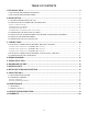
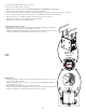
1. TECHNICAL DATA 1.1 AIR DISTRIBUTION (NORMAL OPERATION) Stale air from building 1.2 AIR DISTRIBUTION (DEFROST MODE) Stale air from building Fresh air from outdoors Fresh air to building Stale air to outdoors Stale air to outdoors VF0050A VF0069A NOTE: The dimensions, performance charts, defrost cycle tables and specifications are listed on the specification sheets of the unit. Visit our website at www.broan.com. 2.
2.
2.2 INSTALLING THE DUCTWORK AND THE REGISTERS ! WARNING Never install a stale air exhaust register in a room where there is a combustion device, such as a gas furnace, a gas water heater or a fireplace. 2.2.1 FULLY DUCTED SYSTEM STALE AIR EXHAUST DUCTWORK: • Install registers in areas where contaminants and humidity are produced: Kitchen, bathrooms, laundry room, etc. • Install registers on an interior wall, 6 to 12 inches away from the ceiling OR in the ceiling.
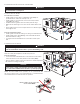
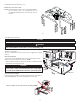
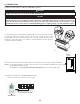
2.2.2 EXHAUST DUCTED SYSTEM (CON’T) EXAMPLE OF AN ATTIC INSTALLLATION NOTE: The AHU blower operation can be synchronized with the unit (see Section 3.3). It is recommended, but not essential that the AHU blower runs when the unit is in operation. VJ0152A 2.2.3 SIMPLIFIED INSTALLATION CAUTION For this type of installation, the furnace/AHU must always be synchronized with the unit. See Section 3.3.
2.2.4 MEASURING THE PRESSURE INSIDE THE DUCTWORK CAUTION This procedure applies to installations where the ductwork of the unit is connected to the return duct of the furnace/AHU (sections 2.2.2 and 2.2.3). Failure to perform this step may severely decrease the performance of the ventilation system and damage the unit and the furnace. After connecting the ductwork as instructed in sections 2.2.2 and 2.2.
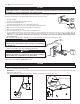
2.4 INSTALLING DUAL EXTERIOR HOOD USING TANDEM® TRANSITION KIT (OPTIONAL) If desired, a Tandem transition kit can be used instead of 2 exterior hoods; but take into account this device will generate approximately an additional 0.2 in w.g. static pressure depending on the installation. If using the Tandem hood, we recommend to use 6-in. ducts to minimize the reduction caused by the tandem hood restriction. The minimum joist opening needed to install the Tandem® transition is 9¾”.
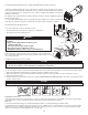
3. CONNECTIONS 3.1 ELECTRICAL CONNECTION TO OPTIONAL MAIN WALL CONTROL ! WARNING Always disconnect the unit before making any connections. Failure to cut power could result in electrical shock or damage to the wall control or electronic module inside the unit. CAUTION Never install more than one optional main wall control per unit. Make sure that the wires do not short-circuit between themselves or by touching any other components on the wall control. Avoid poor wiring connections.
3. CONNECTIONS (CONT’D) 3.1 ELECTRICAL CONNECTION TO OPTIONAL MAIN WALL CONTROL (CONT’D) 3.1.2 ELECTRICAL CONNECTION TO VT4W MAIN WALL CONTROL 3.1.3 ELECTRICAL CONNECTION TO VT6W MAIN WALL CONTROL VT4W M FO R T Z ON E - OFF MIN MAX -5°C 23°F CO XXX XX 5°C 41°F MAIN WALL CONTROL 01/98 NO C NC I OC OL Y R G B # -20°C -4°F REAR VIEW NO C NC I OC OL Y R G B Y G B Y G B VE0323 VE0328A 3.
BK BL BR G O NC NC F1 J10 W BK O O 3 2 1 2 1 4 3 2 1 JU1 3AG TYPE 3A J9 Y 5 4 3 2 1 M H Y 9.
5. SPEED SELECTION The factory set high-speed value for theses units is 129 CFM, and low speed value is approximately 66 CFM. To change these values, the transformer wire taps connections must be changed and/or JU1 jumper must be relocated (see table and illustration below). HRV130FLS ERV130FLS Speed option Connection Pressure (in. w.g.) Supply (CFM) Exhaust (CFM) Power consumption (Watts) Supply (CFM) Exhaust (CFM) Power consumption (Watts) High no. 1 (Default) JU1 in H (1-2) 0.
7.
8. INSTALLER’S TROUBLESHOOTING ! WARNING • A few diagnosis procedures may require the unit to be in operation while proceeding. Be careful with moving and/or live parts. • Risk of electric shocks. Electronic board connections must be checked by qualified personnel only. LED Signal Error Type Action LED flashes GREEN (double blink). Thermistor error (unit still works). Replace the thermistor kit. Supply motor does not work. No Replace the supply motor. Try rotating the supply motor by hand.
8. INSTALLER’S TROUBLESHOOTING (CONT’D) Integrated control LED is OFF. Unit does not work. No Is the power outlet energized? Refer to an electrician. Yes Replace the exhaust motor. Is the fuse on the electronic board blown? No Use a voltmeter. Is there 120 V between J9-4 and J9-1? Yes Use a voltmeter. Is there 120 V at J10? Yes Both speeds do not work, LED sƟll Ňashes RED. Replace the ŽƉƟŽŶĂl wall control. No Replace the electronic board. Use a voltmeter. Is there 9.
9. USING THIS UNIT 9.1 YOUR VENTILATION SYSTEM This unit is designed to provide fresh air to your home while exhausting stale, humid air. By eliminating accumulated pollutants and humidity, it maintains an optimum air quality and an ideal relative humidity. It is equipped with a recovery core that is designed specifically to control excess humidity and reduce ventilation costs by recovering the energy from the exhausted air, and using that same energy to warm the fresh air being supplied.
10. MAINTENANCE ! WARNING Dangerous voltage. During maintenance and repairs, the unit must always be unplugged. We take great care to minimize sharp edges; however, please proceed with caution when handling all components. When cleaning the unit, it is recommended to wear safety glasses and gloves. 10.1 QUARTERLY 1. 2. 3. 4. Disconnect power cord. The door of this unit is hinged and maintained closed by 2 screws. Remove them and set aside. Clean the inside of the door with a damp cloth.
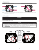
10. MAINTENANCE (CONT’D) 10.2 ANNUAL (AT FALL) 1. • • 2. Repeat steps 1 to 6 from the previous section and continue with the following steps: CAUTION Handle the recovery core with care. Do not disassemble the condensing plate from the heat recovery core. PLATE (HRV UNITS ONLY, SEE SECT. 2.1) Clean the recovery core: VD0443 HRV130FL • • • • 3. 4. 5. 6. CONDENSING ERV130FL Remove the core.
12. WARRANTY This ventilation unit is a high quality product, built and packaged with care. The manufacturer warrants to the original purchaser of its product, that such products will be free from defects for the period stated below, from date of original purchase. For all units, the warranty covers parts only against any operational defect. This 5-year warranty is subject to performance of the core maintenance according recommendations in this manual.
MANUAL DEL USUARIO Y DEL INSTALADOR HRV130FL (No DE PIEZA HRV130FLS), ERV130FL (No DE PIEZA ERV130FLS) REGISTRE SU PRODUCTO EN LÍNEA EN: www.broan-nutone.com/register Para obtener más información, visitar nuestro sitio www.broan-nutone.com VB0247 ANTES DE LA INSTALACIÓN: HRV130FL: LEA LA SECCIÓN 2.1, EN LA PÁGINA 4, PARA OBTENER INFORMACIÓN IMPORTANTE ACERCA DE LA PLACA DE CONDENSACIÓN. TODOS LOS APARATOS: LEA LA SECCIÓN 2.
Este manual utiliza los siguientes símbolos para hacer hincapié en determinada información: ⚠ ADVERTENCIA Se refiere a una instrucción que, si no se sigue, puede provocar lesiones personales graves, incluso causar la muerte. PRECAUCIÓN Denota una instrucción que, si no se sigue, puede dañar gravemente el aparato y/o sus componentes NOTA: Indica la información complementaria necesaria para completar una instrucción. LIMITACIÓN Para instalación residencial (doméstica) solamente.
ÍNDICE 1. DATOS TÉCNICOS ...............................................................................................................4 1.1 DISTRIBUCIÓN DEL AIRE (FUNCIONAMIENTO NORMAL) .......................................................................4 1.2 DISTRIBUCIÓN DEL AIRE (MODO DESCONGELACIÓN)..........................................................................4 2. INSTALACIÓN ................................................................................................................
1. DATOS TÉCNICOS 1.1 DISTRIBUCIÓN DEL AIRE (FUNCIONAMIENTO NORMAL) Aire viciado del edificio 1.2 DISTRIBUCIÓN DEL AIRE (MODO DESCONGELACIÓN) Aire viciado del edificio Aire fresco del exterior Aire fresco hacia el edificio Aire viciado hacia el exterior Aire viciado hacia el exterior VF0050E NOTA: VF0069E Las dimensiones, los gráficos de rendimiento, las tablas del ciclo de descongelación y las especificaciones figuran en las hojas de especificaciones del aparato.
2.1 UBICACIÓN Y MONTAJE DEL APARATO (CONT.
2.2 INSTALACIÓN DE LOS CONDUCTOS Y REGISTROS ! ADVERTENCIA No instale nunca un registro de salida de aire viciado en una habitación donde haya un dispositivo de combustión, tal como una caldera de gas, un calentador de agua a base de gas o una chimenea. 2.2.1 SISTEMA TOTALMENTE EQUIPADO CON CONDUCTOS CONDUCTOS DE SALIDA DE AIRE VICIADO: • Instale los registros en zonas donde se produce humedad y contaminantes: cocina, baño, lavadero, etc.
2.2.2 SISTEMA EQUIPADO CON CONDUCTOS DE AIRE VICIADO (CONTINUACIÓN) EJAMPLO DE UNA INSTALACIÓN EN ÁTICO NOTA: El funcionamiento del ventilador impelente de la AHU puede sincronizarse con el aparato (véase la sección 3.3). Aunque no es esencial, se aconseja que el ventilador impelente de la AHU esté funcionando cuando el aparato esté en marcha. VJ0152E 2.2.3 INSTALACIÓN SIMPLIFICADA PRECAUCIÓN Para este tipo de instalación, la caldera/AHU debe estar sincronizada siempre con el aparato. Véase la sección 3.
2.2.4 MEDICIÓN DE LA PRESIÓN EN EL INTERIOR DE LOS CONDUCTOS PRECAUCIÓN Este procedimiento se aplica a las instalaciones en las que los conductos del aparato están conectados al conducto de retorno de la caldera/AHU (secciones 2.2.2 y 2.2.3). Si no se siguen estas instrucciones, el rendimiento del sistema de ventilación puede disminuir considerablemente y el aparato y la caldera/AHU podrían resultar dañados. Tras conectar los conductos conforme a las secciones 2.2.2 y 2.2.
2.4 INSTALACIÓN DE LA BOCA EXTERIOR DOBLE CON EL KIT DE CAMBIO DE SECCIÓN TANDEM® (OPCIONAL) Si lo desea, puede usar un kit de cambio de sección Tandem en lugar de 2 bocas exteriores; pero tenga en cuenta que este dispositivo generará una presión estática adicional de 0,2 pulg. de agua, según la instalación. Si se usa una boca Tandem, aconsejamos el uso de conductos de 6 pulg. para minimizar la reducción causada por la restricción de la boca Tandem.
3. CONEXIONES 3.1 CONEXIÓN ELÉCTRICA CON EL CONTROL MURAL PRINCIPAL OPCIONAL ! ADVERTENCIA Desconecte siempre el aparato antes de efectuar cualquier conexión. De no cortar la alimentación, podría producirse un choque eléctrico o dañarse el control mural o el módulo electrónico dentro del aparato. PRECAUCIÓN No instale nunca más de un control mural principal opcional por aparato. Compruebe que los cables no se cortocircuiten entre ellos o tocando otros componentes del control mural.
3. CONEXIONES (CONT.) 3.1 CONEXIÓN ELÉCTRICA CON EL CONTROL MURAL PRINCIPAL OPCIONAL (CONTINUACIÓN) 3.1.2 CONEXIÓN ELÉCTRICA CON EL CONTROL MURAL PRINCIPAL 3.1.3 CONEXIÓN ELÉCTRICA CON VT4W VT6W EL CONTROL MURAL PRINCIPAL VISTA POSTERIOR DEL CONTROL MURAL VT4W - OFF MIN MAX -5°C 23°F # CO M FO R T Z ON E 5°C 41°F XXX XX PRINCIPAL 01/98 NO C NC I OC OL Y R G B -20°C -4°F NO C NC I OC OL Y R G B A Y V N G B VE0328E VE0323 3.
12 AM AZ B C NE 120 VCA 60 Hz NE AZ C SC SC NARANJA PÚRPURA ROJO VERDE SIN CONEXIÓN SC V J4 NA P R V 1 2 3 J6 J7 J5 2 1 2 1 1 2 3 3A J9 B NE J10 2 1 4 3 2 1 5 4 3 2 1 M H JU1 3 2 1 AM NA AM NA Clase 2 de 9,5 V Clase 2 de 24 V Opcional TIPO 3AG F1 T1 R1 1 2 ICP J13 1 2 J20 10 9 8 7 6 5 4 3 2 1 J14 V R ref: 24228_REV-B TARJETA ELECTRÓNICA A1 J12 J11 TERMISTOR J8 CABLEADO DE FÁBRICA DE TENSIÓN DE LÍNEA CABLEADO DE FÁBRICA DE BAJA TENSIÓN DE CLASE 2 CABLEADO IN SITU
5. SELECCIÓN DE LA VELOCIDAD El valor de alta velocidad ajustado en fábrica para estas unidades es de 129 pi3/min y el valor de baja velocidad es aproximadamente de 66 pi3/min. Para cambiar estos valores, las conexiones de los hilos del transformador y/o el puente JU1 deben ser cambiadas (vea la tabla y la ilustración abajo). HRV130FLS ERV130FLS Opción de velocidad Conexión Presión (pulg.
7. PIEZAS DE RECAMBIO 12 13 10 1 4 2 1 3 11 6 5 14 2 7 3 8 9 No DESCRIPCIÓN NÚMERO DE PIEZA 1 2 3 4 Conjunto de la compuerta de contracorriente Puerto de metal de 5 pulg.
8. SOLUCIÓN DE PROBLEMAS DEL INSTALADOR ! ADVERTENCIA • Algunos procedimientos de diagnóstico pueden exigir que el aparato esté funcionando durante el procedimiento. Tenga cuidado con las piezas en movimiento o móviles. • Riesgo de descarga eléctrica. Las conexiones de la tarjeta electrónica sólo deben verificarse por personal cualificado. Señal LED Tipo de error Acción El LED parpadea en VERDE (parpadeo doble) Error de termistor (el aparato aún funciona).
8. SOLUCIÓN DE PROBLEMAS DEL INSTALADOR (CONT.) El LED del control integrado está apagado. El aparato no funciona. ¿Recibe alimentación la toma de corriente? No Consulte a un electricista. SuƐƟƚƵLJa el motor de extracción de aire Ninguna de las velocidades funciona, el LED parpadea en rojo todavía. SuƐƟƚƵLJa el control mural opcional. ¿Está fundido el fusible en la tarjeta electrónica? Sí ĞũĞ ĚĞ ƵƟůŝnjĂƌ Ğů aparato y póngase en contacto con el servicio de asistencia técnica.
9. USO DE ESTE APARATO 9.1 SU SISTEMA DE VENTILACIÓN Este aparato está pensado para proporcionar aire fresco a su casa y extraer el aire viciado y húmedo. Al eliminar la humedad y los contaminantes acumulados, el sistema mantiene un aire de calidad óptima y una humedad relativa ideal.
10. MANTENIMIENTO ! ADVERTENCIA Tensión peligrosa. El aparato debe estar siempre desenchufado durante las operaciones de mantenimiento y reparación. Aunque procuramos minimizar los bordes cortantes, tenga cuidado al manipular todos los componentes. Al limpiar el aparato, se aconseja llevar lentes y guantes de seguridad. 10.1 TRIMESTRAL 1. Desconecte el cable de alimentación. 2. La puerta de este aparato lleva bisagras y se mantiene cerrada con 2 tornillos. Retírelos y póngalos a un lado. 3.
10. MANTENIMIENTO (CONT.) 10.2 ANUAL (EN OTOÑO) 1. Repita las etapas 1 a 6 de la sección anterior y continúe con las que se exponen a continuación: PLACA DE PRECAUCIÓN • Manipule con cuidado la unidad de recuperación. • No desmonte la placa de condensación de la unidad de recuperación de calor. CONDENSACIÓN (APPARATOS HRV ÚNICAMENTE, VÉASE LA 2. Limpie la unidad de recuperación: SECCIÓN HRV130FL • • • • 3. 4. 5. 6. 2.1) VD0443 ERV130FL Retire la unidad.
12. GARANTÍA Este aparato de ventilación de Broan es un producto de gran calidad, fabricado y empacado con cuidado. Broan garantiza al comprador original de sus productos que dichos productos están libres de defectos por el periodo de tiempo indicado más adelante, a partir de la fecha de compra original. La garantía de todos los aparatos Broan cubre las piezas únicamente contra cualquier defecto que pudiera perjudicar su funcionamiento. Su duración es de cinco (5) años.