
User Guide

10
3. CONNECTIONS
3.1 ELECTRICAL CONNECTION TO OPTIONAL MAIN WALL CONTROL
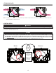
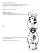
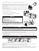
Use the terminal connector included in the installation kit to perform the electrical connection
for main and optional wall controls. Check if all wires are correctly inserted in their
corresponding holes in the terminal block. A wire is correctly inserted when its orange
receptacle is lower than another one without a wire. On illustration at right, wire A is
correctly inserted, but not wire B.
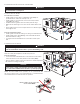
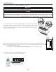
3.1.1 ELECTRICAL CONNECTION TO VT7W MAIN WALL CONTROL
(RECIRCULATION MODE NOT AVAILABLE FOR THESE UNITS)
NO C NC I OC OL Y R G B
VE0250
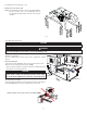
Once the wall control connections have been made, insert the terminal connector in the electrical compartment.
NOTES : For information about the operation of the wall control, refer to the Main and auxiliary wall controls user
guide, available at www.broan.com.
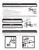
The integrated control must be turned OFF (no LED lighted on) to use an optional main control.
Always disconnect the unit before making any connections. Failure to cut power could result in electrical shock or
damage to the wall control or electronic module inside the unit.
Never install more than one optional main wall control per unit. Make sure that the wires do not short-circuit
between themselves or by touching any other components on the wall control. Avoid poor wiring connections. To
reduce the risk of electrical interference (noise), do not run wall control wiring next to control contactors or near
light dimming circuits, electrical motors, dwelling/building power or lighting wiring, or power distribution panel.
CAUTION
WARNING
!
VE0272
A
B
VD0430
TERMINAL
CONNECTOR