
Manual

D. Youcanfightthefirewithyourbacktoanexit.
*Basedon"KitchenFireSafetyTips"publishedby
NFPA.
CAUTION
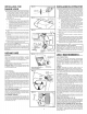
1. For general ventilating use only. Do not use to exhaust
hazardous or explosive materials and vapors.
2. To avoid motor bearing damage and noisy and/
or unbalanced impellers, keep drywall spray,
construction dust, etc. off power unit.
3. Your hood motor has a thermal overload which will
automatically shut off the motor if it becomes
overheated. The motor will restart when it cools
down. If the motor continues to shut off and restart,
have the hood serviced.
4. For bestcapture of cooking impurities, your range hood
should be mounted 18-24" above the cooking surface.
5. Please read specification label on product for further
information and requirements.
TOOLS AND
MATERIALS REQUIRED
TOOLS
[] Drill, electric or ratchet drive
[] 1-1/4" Spade bit
[] Common head and phillips head screwdriver
[] Pliers
[] Tape measure or ruler and pencil
rFor Ducted Installations ONLY: I
I [] Saber saw or drywall saw I
/ [] Metal snips j
MATERIALS
[] Electrical wiring and supplies of type to comply
with local codes
r[] Roof or wall cap I
I [] Roof cement or caulk I
[] Duct and duct tape
L J
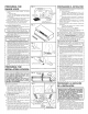
For Installation on Kitchen Cabinets with Recessed
Bottoms Only:
[] Two 1" x 2" x 12" (approximate length) wood strips
(purchase locally)
[] Four 1-1/4" long flat head wood screws (purchase
locally) to fasten strips to cabinet bottom
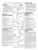
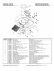
PLANNING DUCTWORK
INSTALLATION
Begin planning ductwork by deciding where the duct
will run between the range hood and the outside. For
best performance, use the shortest possible duct run
and a minimum number of elbows. There are several
choices shown - FIGS. 1A - 1E.
In more complex ducting situations, a 3-1/4" rectan-
gular ducting range hood can be converted to a round
duct by means of a transition.
FIG. 1A. Ducting directly through the wall (for range
hoods mounted on an exterior wall). Shown are two
ways to duct through an outside wall. If a wall cap is
used directly off the back of the hood, special care
must be taken to make sure that the damper in the
damper/duct connector on the hood and damper in
the wall cap do not interfere with each other when the
hood is operating. This could result in either inad-
equate air delivery or back drafts. If this condition does
exist, remove the hood damper flap. Sometimes when
using a wall cap it is easier to duct vertically and then
use an elbow as shown in FIG. lB.
FIG. lC. Ducting straight up through the roof using
3-1/4" x 10" rectangular duct. (For single story in-
stallations.)
FIG. 1D. Ducting between the ceiling joists (for multi-
story installations) or through the soffit space above
the cabinets (where the soffit connects to an outside
wall).
FIG. 1E. Straight up through the roof using 3-1/4" x
10" to 6" round duct transition and 6" round duct (for
single-story installations).
FIG. 1F. Straight up through the roof using 7" round
duct (for single-story installations).
FIG.
WALLCAP639OR 649
CASQUETEDEPARED639 0 649
FIG. 1B WALLCAP639 OR649
_x ASQUETEDEPARED
639 O 649
10" DUCT401
_1 _._ UCTO DE3-1/4"x 10''401
FIG. lC _ _ ROOFCAP634 OR644
_ _ CASQUETEDE
"_ _ TECHO634 O 644
II ,,... 3-1/4..x10..DUCT401
II DUC4TODE 401
@
FIG. 1D
ADJUSTABLEELBOW4t9 WALLCAP641
CODOAJUSTABLE419 CASQUETEDE
PARED641
f:_>, --
6" ROUNDDUCT4 3-1/4" x 10" TO6"
DUCTOREDONDODE t [ ROUNDDUCT
6" 406 _ TRANSITION4t 1
TRANSICIONDE
3-1/4" x 10" A
UNDUCTO
REDONDO
DE6"411
FIG. 1E ROOFCAP634 OR644
CASQUETEDETECHO634 O 644
FIG. 1F
._-'-_ _ ROOF CAP 634
_ _ OASQUETE DE
"X_ TECHO 634
7" ROUND DUCT 407 I _ I
DUOTOREDONDOI I
DE 7" 407
II
I I _ MODEL BP87
_ DAMPER
/ I REGISTRO
\1 _ _j DETIRO
MODELO BP87
PRECAUCION
1. Solamente para uso general de ventilaci6n. No utilice parR
descargar materiales o vapores riesgosos o explosivos.
2. ParR evitar daSos al motor y evitar que las navajas del
abanico emitan mucho ruido o esten fuera de balance,
mantenga el motor libre de pelusa, polvo, etc.
3. El motor de su extractor tiene dispositivo de sobrecarga
termica, al cuRl automaticamente apagara el motor si
se sobrecalienta. El motor funcionardt de nuevo cuando
se enfrfe. Si el motor continua apagandose y arrancando,
hagalo componer.
4. ParR obtener mejores resultados en la captura de los
vapores de la estufa, el extractor debe montarse a entre
18 y 24 pig. sobre las hornillas de la estufa.
5. Por favor lea la etiqueta con las especificaciones del
equipo parR otros requisitos y mayor informacion.
HERRAMIENTAS Y
MATERIALES QUE SE
REQUIEREN
HERRAMIENTAS
[] Taladro, electrico o trinquete
[] Broca tipo paiR de 1-1/4"
[] Destornillador de ranura o tipo phillips
[] Pinzas o tenazas
[] Medidor de cinta o regla y lapiz
rp'_rra instalaciones con ducto SOLAMENTE: 1
I [] Sierra tipo sable o sierra parR tabiques I
/ [] Alicate parR cortar j
MATERIALES
[] Suministros y alambre electrico del tipo que cumplen
con los codigos locales
rE_ Casquete de techo o pared 1
I [] Cemento o pega de techa o material de calafatear I
I
o rellenar
I
/ [] Ductos y cinta aislante parR ductos j
ParR instalaci6n en gabinetes de cocina con la parte infe-
rior ahuecada solamente:
[] Dos tiras de madera 1" x 2" x 12" (largo aproximado)
(compreselas Iocalmente)
[] Cuatro tornillos para madera de cabeza plana de 1-1/4"
de largo (c6mpreselas Iocalmente) parR sujetar las tiras
de madera a la parte inferior de gabinete
PLANIFICANDO LA
INSTALACION DE LOS
DUCTOS
Comience el trabajo de los ductos decidiendo el camino
que el ducto tomara entre el extractor y la parte exterior
de la casa. ParR mejor rendimiento, use el camino de ducto
ma.s corto posible y un mfnimo de codos. Se muestran
varias elecciones - FIGS. 1A - 1E.
En situaciones de paso del ducto m_ts complejas, el ex-
tractor con conexi6n para ducto rectangular puede
convertirse en conexi6n redonda usando una transici6n.
FIG. 1A. Pasando el ducto directamente a traves de la
pared (parR los extractores que estan instalados en una
pared exterior). Se muestran dos maneras de pasar el
ducto a traves de la pared exterior. Si se usa un casquete
de pared directamente en la parte de atra.s del extractor
hay que asegurarse que el regulador en el conector entre
ducto y regulador en el extractor, y el regulador en el
casquete de pared no interfieran el uric con el otro cuando
el extractor este operando. Esto podria resultar en paso
de aire inadecuado o corrientes invertidas. Siesta
condicion existe, quite la hoja instalada en el regulador
del extractor. A veces cuando se usa un casquete de pared
es ma.s facil pasar el ducto verticalmente y usar un codo
como se muestra en FIG. lB.
FIG. lC. Haciendo un ducto directamente al techo usando
un ducto rectangular de 3-1/4" x 10" (parR instalaciones
en un piso solamente).
FIG. 1D. Instalando un ducto entre las vigas del techo
(parR instalaciones en mdts de un piso) o a traves del
espacio de sofito arriba de los gabinetes (cuando el sofito
esta conectado a una pared exterior).
FIG. 115. Directamente hacia el techo usando transicion
de 3-1/4" x 10" aun ducto redondo de 6" y ducto redondo
de 6" (parR instalaciones de un piso).
FIG. 1F. Directamente hacia el techo usando ducto
redondo de 7" (parR instalaciones de un piso).