
Manual

PREPARING THE
RANGEHOOD
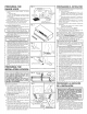
• Unpack hood and check contents• You should
receive:
1 - Aluminum Filter
1 - 3-1/4" x 10" Damper/Duct Connector (mounted
inside of hood for shipping only) (Save screws
for mounting.)
1 - 7" Round Duct Plate (mounted on top of hood)
(not shown) (Save screws for mounting.)
2. Remove 7" round duct plate from top of hood.
Set duct plate aside - with mounting screws.
3. Remove wiring box cover. Under cover find:
1 - Plastic Bag containing loose mounting hardware
For Ductfree Installations Only:
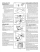
4. For ductfree installation, remove louver cover from
front (or inside) of hood. (FIG. 3)
NOTE I
I Louvers on front of hood must be open and
visible for hood to function in ductfree mode.
5. Remove either top or rear electrical knockout de-
pending upon whether wiring will enter hood from
wall or cabinet. (FIG. 4)
I-D_'TE'D INSTALLATION ONLY
NOTE I
I Louver cover must be installed as shown inFigure 3 to function in ducted mode,
6. Remove appropriate duct knockout on hood by
inserting screwdriver into edge of knockout and
breaking tabs holding knockout to hood. You may
have to tap screwdriver with hammer to break tabs.
Peel knockout back with pliers• (FIG. 5)
7. Fit damper/duct connector over opening and secure
in place with black sheet metal screws• (FIG. 6)
Hinge pins and damper/duct connector should be
toward top of hood for ducting through wall or to-
ward back of hood for ducting through cabinet
above hood. Seal joint between damper/duct con-
nector and hood with duct tape.
8. 7" round ducted discharge only: Re-install 7"
round duct plate removed in Step #2 under "PRE-
PARING THE RANGE HOOD" section. For best
performance, line up the 7" round duct plate
with the 7" round opening on hood. Mount duct
plate to hood with 2 screws from duct plate and 2
screws from 3'A"x 10" damper. Install a 7" round
damper (purchase separately). Damper flap must
open freely in direction of air flow (away from range
L hood), j
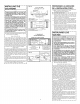
PREPARING THE
INSTALLATION LOCATION
NOTE
MOUNT HOOD SO THAT BOTTOM OF HOOD IS
18"-24" ABOVE COOKING SURFACE. TOP
FRONT EDGE OF HOOD SHOULD BE FLUSH
WITH FRONT OF CABINET FRAME.
IF DISTANCE BETWEEN WALL AND FRONT OF
CABINET FRAME IS MORE THAN 12" THERE
WILL BE A SPACE BETWEEN BACK OF HOOD
AND WALL. THIS IS NORMAL.
OMIT STEP 9 if range hood will be installed under
cabinets with flush bottom.
9. (For installation on recessed bottom cabinets
only) Attach a wood filler strip at each side of
recessed area under cabinet. (Use two 1" x 2"
strips cut to length.) If recess is more than 1" use
thicker strips• Attach strips with 1-1/4" screws
about 3" from each end. See FIG. 7.
10.Measure and mark the following (FIGS. 7 & 8):
a) Electrical line._penmg
E Duc e _ ]
11. Drill four pilot holes in corners of marked duct
opening as shown and cut opening with saber
saw or keyhole saw.
12. Use 1-1/4" drill bit to drill opening for electrical
connection in wall or cabinet•
13. Hold hood up against cabinet bottom and trace
keyhole slots onto cabinet bottom of filler strips•
14.Screw the four supplied 7/8" wood screws for
mounting the hood into the exact center of the
narrow end of the keyhole slots marked under-
neath the cabinet• Allow 3/8" of the screws to
project, so the hood can be fitted into place•
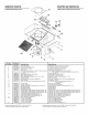
FIG. 2
OERRADURA _ ,
LjL_--J
I WIRING BOX COVER
TAPA DELA CAJA DE
ALUMINUM FILTER _!EADO
FILTRO DE ALUMINIO
/
DAMPERIDUCT CONNECTOR
OONECTOR AL REGULADOR'DUCTO
FIG. 4
o\
/
/
I'
,/
FIG. 5 " .
FIG. 7
-\ _ ....................\
"_ _/
\
1
\_& CUT STRIPS TO FiT _[_._ /
\_#_, ._I- CORTELASTIRASRARA "_H.:.-_,_]!
_'_ QUE QUEPAN _
DU'_T--OPE--N_GS _,\ //
ABERTURA PARA CENTER LINE .
• WIDTH OF
RANGE HOOD
ANCHO DEL
EXTRACTOR
ELECTRICAL WIRING OPENING
ABERTURA PARA EL
CABLEADO ELECTRICO
PREPARANDOEL EXTRACTOR
1. Desempaque el extractor y revise el contenido de la
caja. Usted debe de encontrar:
1 - Filtro de aluminio
1 - Conector de ducto/regulador de 3-1/4" x 10"
(montado dentro del extractor para embarque
solamente) (Guarde los tornillos para el monta-
je.)
1 - Placa del conducto redondo de 7" (montado en
del extractor) (no se muestra) (Guarde los torni-
Ilos para el montaje.)
2. Quite la placa del conducto redondo de 7" de la parte
superior de la campana. Coloquela aparte, con los
tornillos de montaje.
3. Quite la cubierta de la caja de cableado. Bajo la tapa
encontrara:
1 - Una bolsa de plastico que contiene herrajes
sueltos para instalaciOn
Para instalaciones sin ducto SOLAMENTE:
4. Para instalaciones sin ducto, quite la tapa de la reji-
Ilas de la parte frontal del extractor. (FIG. 3)
NOTA
I Las rejillas que se encuentran al frente de la campana I
I
deben estar abiertas y visibles para que la campana
funcione sin conducto.
5. Quite la tapa de quitar golpeando electrica de arriba
o atra.s dependiendo en donde entra el cableado al
extractor de la pared o del gabinete. (FIG. 4)
_N"_A-_CTO'N' CON DUCTO SOLAMENTE 1
i NOTA
La cubierta de las rejillas se debe instalar como se
muestra en a figUraconducte.3para que funcione con e
6. Quite la placa de quitar golpeando en el extractor
insertando un destornillador en el filo y rompiendo
las conexiones que Io sostienen al extractor, Es
posible que tenga que golpear el destornillador con
un martillo para romper estas uniones. Pele la tapa
de quitar golpeando hacia atras con una tenaza.
(FIG, 5)
7. Junte el conector del regulador/ducto sobre la aber-
tura y sujetelo en su sitio con tornillos negros de
metal para lamina, (FIG, 6)
Los pasadores de bisagra y el conector del regula-
dor/ducto deben de estar hacia la parte de arriba
del extractor para pasar el ducto a traves de la pa-
red o hacia la parte de atras del extractor para pa-
sar el ducto a traves de gabinete encima del
extractor, Selle la union entre el conector regula-
dor/ducto con cinta de ducto.
8. Solo para descargas con conducto redondo de
7": Vuelva a instalar la placa del conducto redondo
de 7" que quito en el paso 2 de la secciOn "PREPA-
RANDO EL EXTRACTOR." Para obtener un mejor
rendimiento, alinee la placa del conducto redondo
de 17.8 cm (7") con la abertura redonda de 17.8
cm (7") de la campana. Monte la placa del conduc-
to a la campana con dos tornillos desde la placa
del conducto y con dos tornillos desde el tiro de 8.3
x 25,4 cm (3 W' x 10"). Instale un regulador de tiro
redondo de 7" (se compra por separado). La aleta
del regulador se debe abrir libremente en direcciOn
del fiujo de aire (en sentido contrario a la campana
de la estufa).
L J
PREPARANDOLA UBICACION
DE LA INSTALACION
NOTA
MONTE EL EXTRACTOR DE MANERAQUE LA PARTE
INFERIOR EST# 18"-24" ENCIMA DE LA SUPERFICIE
DE LA COCINA. LA PARTE SUPERIOR DEL FRENTE
DEL EXTRACTOR DEBE DE ESTAR A RAS CON EL
FRENTE DEL ARMAZON DEL GABINETE.
SI LA DISTANCIA ENTRE LA PARED Y LA PARTE FRON-
TAL DEL ARMAZ(_N DEL GABINETE ES M#.S DE 12"
HABR,&,UN ESPACIO ENTRE LA PARTE DE ATR,&.SDEL
EXTRACTOR Y LA PARED. ESTO ES NORMAL.
OMITA PASO 7 si el extractor estara instalado debajo de
un gabinete con la parte inferior plana.
9. (Para instalacion en gabinetes ahuecados solamente)
Sujete una tira de madera a cada lado de la parte
inferior ahuecada debajo del gabinete. (Use dos tiras
de madera de 1" x 2" cortadas al largo necesario.) Si
el ahuecamiento es mdts de 1" use tiras mas gruesas.
Sujete las tiras con tornillos de 1-1/4" a una distancia
de mas o menos 3" del extremo. Vease FIG. 7.