INSTALLATION INSTRUCTIONS HRV90H AND ERV90HC Model no.: HRV90HT (HRV with ports on top) VB0082 Model no.: HRV90HS (HRV with ports on sides) VB0081 Model no.: ERV90HCT (ERV with ports on top) VB0080 Model no.: ERV90HCS (ERV with ports on sides) VB0079 RESIDENTIAL USE ONLY READ AND SAVE THESE INSTRUCTIONS 06010C rev.
ABOUT THIS MANUAL Because of the large amount of models covered by this publication, the illustrations are typical ones. Some details of your unit may be slightly different than the ones shown. Please take note that this manual uses the following symbols to emphasize particular information: ! WARNING Identifies an instruction which, if not followed, might cause serious personal injuries including possibility of death.
TABLE OF CONTENTS 1. TECHNICAL DATA . . . . . . . . . . . . . . . . . . . . . . . . . . . . . . . . . . . . . . . . . . . . . . . . . . . . . . . . . . . .4-6 1.1 1.2 1.3 1.4 1.5 1.6 2. TYPICAL INSTALLATIONS . . . . . . . . . . . . . . . . . . . . . . . . . . . . . . . . . . . . . . . . . . . . . . . . . . . . . . . .7-8 2.1 2.2 2.3 2.4 3. 9. INSPECT THE CONTENT OF THE BOX . . . . . . . . . . . . . . . . . . . . . . . . . . . . . . . . . . . . . . . . . . . . . . . . . . . . . . . .
1. TECHNICAL DATA 1.1 AIR DISTRIBUTION (NORMAL OPERATION) HRV ERV EXHAUST AIR FROM BUILDING FRESH AIR FROM OUTSIDE EXHAUST AIR FROM BUILDING FRESH AIR TO BUILDING EXHAUST TO BUILDING FRESH AIR TO OUTSIDE FRESH AIR FROM OUTSIDE AIR EXHAUST AIR TO OUTSIDE VF0039 VF0038 1.
1. TECHNICAL DATA (CONT’D) 1.4 PERFORMANCE CHARTS 1.4.1 HRV UNITS VENTILATION PERFORMANCE EXT. STATIC PRESSURE PA IN. W. G. 25 .1 50 .2 75 .3 100 .4 125 .5 150 .6 175 .7 200 .
1. TECHNICAL DATA (CONT’D) 1.5 DIMENSIONS 1.5.1 DIMENSIONS FOR PORTS ON SIDES UNITS HRV 27 1/16” (688 mm) 4” (102 mm) 19 13 /16” (503 mm) 22 9/16” (574 mm) 6” (152 mm) 12 3 /16” (310 mm) 13¾” (349 mm) 2” (51 mm) VK0055A ERV 27 1/16” (688 mm) 4” (102 mm) 19 13 /16” (503 mm) 22 9 /16” (574 mm) 12 3 /16” (310 mm) 6” (152 mm) 2” (51 mm) VK0057A 1.5.
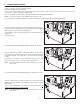
2. TYPICAL INSTALLATIONS Installations may vary according to the type of unit and the ports configuration (top or sides). Use the following illustrations as guidelines to help you decide on how the unit will be installed. All the units should be hung from the joists. In every case, bathroom fans and a range hood should be used to exhaust stale air. Also, for homes with more than one level, we recommend one exhaust register at the highest level.
2. TYPICAL INSTALLATIONS (CONT’D) 2.4 INSTALLATION 2.4.1 FOR ERV UNITS ONLY GEOGRAPHICAL LOCATION The ERV units are created to meet specific requirements related to geographical locations. Take a look at the map below; the shaded area shows the limits where the ERV unit can be installed. However, there is no geographical limitation for installing an HRV unit.
3. INSTALLATION 3.1 INSPECT THE CONTENTS OF THE BOX • Inspect the exterior of the unit for shipping damage. Ensure that there is no damage to the door, door latches, power cord, etc. • Remove and discard the 2 transport brackets (A) and open the door. Discard the styrofoam fillers (ERV units only) and remove the hardware kit from the unit. Inspect the interior of the unit for damage. Ensure that heat or energy recovery core, core filters, insulation, dampers, etc. are all intact. A VD0183 3.
3. INSTALLATION (CONT’D) 3.4 HOW TO HANG THE UNIT Hang the unit with the 4 chains, hooks and springs provided. VD0185 VD0184 CAUTION Make sure the unit is level. 3.5 PLANNING OF THE DUCTWORK • Keep it simple. Plan for a minimum of bends and joints. • Keep the length of insulated ducts to a minimum. • Do not ventilate crawl spaces or cold rooms. Do not attempt to recover the exhaust air from a dryer or a range hood. This would cause clogging of the filters and recovery module.
3. INSTALLATION (CONT’D) 3.6 INSTALLING THE DUCTWORK 3.6.2 AND REGISTERS (CONT’D) CENTRAL DRAW POINT SYSTEM (AS ILLUSTRATED IN SECTION 2.2) Stale air exhaust ductwork Same as for Fully Ducted System, described on point 3.6.1. Fresh air distribution ductwork ! WARNING When performing duct connections, always use approved tools and materials. Respect all corresponding laws and safety regulations. Please refer to your local building code.
3. INSTALLATION (CONT’D) 3.6 INSTALLING THE DUCTWORK 3.6.3 AND REGISTERS (CONT’D) SIMPLIFIED INSTALLATION (AS ILLUSTRATED IN SECTION 2.3) ! WARNING When performing duct connections, always use approved tools and materials. Respect all corresponding laws and/or safety regulations. Please refer to your local building code. 0 CAUTION When performing duct connections to the furnace supply duct, this duct must be sized to support the additional airflow produced by the HRV/ERV. Also, use a steel duct.
3. INSTALLATION (CONT’D) 3.7 CONNECTING THE DUCTS TO THE UNIT Insulated flexible ducts Use the following procedure for connecting the insulated flexible ducts to the port of the unit (Exhaust air to outside and Fresh air from outside ports). CAUTION Make sure the balancing dampers are set to their appropriate position before connecting the ducts to the ports. See Section 3.3. VJ0039 Pull back the insulation to expose the flexible duct.
3. INSTALLATION (CONT’D) 3.8 INSTALLING THE TANDEM TRANSITION KIT (CONT’D) 3.8.1 CONNECTION TO TANDEM TRANSITION 1. For each duct, pull back the insulation to expose the interior flexible duct. 2. Connect the interior flexible duct to the smaller part of the Tandem Transition (5” oval) using a tie wrap. 3. Pull the insulation over the joint. Pull the vapor barrier over the insulation. 4. Apply duct tape gently to the joint in order to make an airtight seal. See figures below.
3. INSTALLATION (CONT’D) 3.8 INSTALLING THE TANDEM TRANSITION KIT (CONT’D) 3.8.4 CONNECTING TANDEM TRANSITION TO THE DUAL EXTERIOR HOOD (CONT’D) XMAS TREE 2. Join the end of the Tandem Transition to the rear of the exterior backplate. Secure with 2 Xmas tree pins and seal properly with duct tape. VD0085 CAUTION The exterior backplate must be installed with the word “TOP” pointing upward. 3. Using 4 no. 8 x 1½” screws, mount the the exterior backplate to the exterior wall.
3. INSTALLATION (CONT’D) 3.9 INSTALLING 2 EXTERIOR HOODS Choose an appropriate location to install the exterior hoods: • There must be a minimum distance of 6 feet (1.8 m) between the hoods to avoid cross-contamination • There must be a minimum distance of 18 inches (457 mm) from the ground ! WARNING Make sure the intake hood is at least 6 feet (1.
4. CONTROLS 4.1 INTEGRATED CONTROL WARNING AVERTISSEMENT Risk of electric shock. Before performing any maintenance or servicing, always disconnect the unit from its power source. Danger d’électrocution. Débranchez toujours l’appareil avant d’entreprendre des travaux d’entretien ou de réparation. CAUTION ATTENTION Unscrew both screws to open the electrical Dévisser les deux vis pour ouvrir le compartiment compartment. To completely remove, detach électrique.
4. CONTROLS (CONT’D) 4.2 ELECTRICAL CONNECTION TO OPTIONAL WALL CONTROLS (CONT’D) 4.2.1 ELECTRICAL CONNECTION TO VT4W MAIN WALL CONTROL MAIN WALL CONTROL AIN WALL LITE-TOUCH CONSTRUCTO and CONTROL SIMPLE-TOUCH CONSTRUCTO REAR REARVIEW VIEW M VT4W NO C NC I OC OL Y R G B Y OC G B G B VE0100A 4.2.
4. CONTROLS (CONT’D) 4.4 OPTIONAL AUXILIARY WALL CONTROLS OPERATION 4.4.1 20-MINUTE LIGHTED PUSH-BUTTON TIMER Set the push-button timer to ON. The fan motors will then operate at high speed for 20 minutes and the indicator will light up. ON To stop activation, push one time; the unit will then get back to previous selection. 4.4.2 60-MINUTE CRANK TIMER VC0084 OFF TURN PAST 20 10 20 This control makes the system operate at high speed for periods varying from 10 to 60 minutes.
- 20 - VE0130A Supply fan M2 motor Supply fan motor C2 capacitor Exhaust fan motor C1 capacitor Exhaust fan motor M1 BN BL BN 1 BK BK J2 2 1 1 2 3 1 2 3 2 1 J8 1 J9 MED HI 3 2 5 4 3 2 1 BN F1 W1 W G BK J10 4 321 See note 1 2 1 120 V, 60 Hz J4 J6 J7 J5 Y 12 J11 J12 J3 12 54321 J1 R1 COLOR CODE BK BLACK BL BLUE BN BROWN G GREEN R RED W WHITE Y YELLOW nc no connection Critical characteristic.
7. BALANCING THE UNIT To avoid balancing, the difference between stale air ducts total length and fresh air ducts total length must not exceed 50 ft. However, even if the stale air ducts and fresh air ducts lengths are almost equal, your local building codes may require balancing the unit. If the unit does not need to be balanced, shut all the pressure taps (located on the unit door) with the small plastic plugs included in the hardware kit. 7.
8. CONNECTING THE DRAIN (HRV UNITS ONLY) A VD0181 From the inner side of the unit door, using the provided drain tube, punch out both drain holes (A). VO0091 In order to keep the drain pan intact, hand tighten the 2 plastic drain fittings to the unit door using the gaskets and nuts as shown. TIE-WRAP VO0092 VO0093 Cut 2 sections of plastic tubing, about 12” (305 mm) long and attach them to each drain fitting. Join the 2 short sections to the “T” junction and main tube as shown.
9. MAINTENANCE ! WARNING Risk of electrical shocks. Before performing any maintenance or servicing, always disconnect the unit from its power source. Since this guide covers both HRV and ERV units, top and side ports, the illustrations shown in the maintenance procedures are typical. The following procedures applies for both HRV and ERV units. Refer to pictures below to identify the inner parts of your unit.
9. MAINTENANCE (CONT’D) 9.1 SEMI-ANNUAL MAINTENANCE (CONT’D) 4. Clean the inside walls of the unit with a clean damp cloth, then wipe with a clean dry one. 5. Wash the 2 core filters under hot water with mild soap. Rinse thoroughly and let dry completely before reinstalling on the core. 6. Remove the dust on the core using a vacuum cleaner and a soft brush attachment.
10.
11. TROUBLESHOOTING If the integrated control LED of the unit is flashing, this means the unit sensors detected a problem. See the table below to know where on the unit the problem occurs. LED flashes GREEN. LED flashes AMBER. LED flashes RED. • Thermistor error. • Damper error. • The door is open and the unit is not unplugged. • Exhaust motor error. Problems Possible causes You should try this 1. Unit does not work. • The circuit board may be defective. • Unplug the unit.
10.
11. SOLUCIÓN DE PROBLEMAS Si el diodo del control integrado del aparato parpadea es que los sensores han detectado un problema. Vea la tabla siguiente para saber dónde se ha producido dicho problema. El diodo parpadea en VERDE. El diodo parpadea en ÁMBAR. El diodo parpadea en ROJO. • Error del termistor. • Error de un registro. • La puerta está abierta y el aparato. no está desenchufado. • Error en el motor de extracción. Sustituya todo el conjunto de la abertura (aire puro del exterior). Vaya al punto 6.
MANUAL DE INSTALACIÓN MODELOS HRV90H Y ERV90HC Modelo n.°: HRV90HT (HRV con aberturas en la parte superior) VB0082 VB0081 Modelo n.°: ERV90HCT (ERV con aberturas en la parte superior) VB0080 Modelo n.°: HRV90HS (HRV con aberturas laterales) Modelo n.°: ERV90HCS (ERV con aberturas laterales) VB0079 SÓLO PARA USO RESIDENCIAL LEA Y CONSERVE ESTAS INSTRUCCIONES 06010C rev.
ACERCA DE ESTE MANUAL Dado el gran número de modelos de los que trata este manual, las ilustraciones son de carácter general. Algunos detalles de su aparato pueden ser ligeramente distinos de los que se muestran aquí. Tenga en cuenta que en este manual se emplean los siguientes símbolos cuando se quiere insistir en una información determinada: ! ADVERTENCIA Se refiere a una instrucción que, de no siguirse, podría causar heridas corporales graves e incluso la muerte.
ÍNDICE 1. DATOS TÉCNICOS . . . . . . . . . . . . . . . . . . . . . . . . . . . . . . . . . . . . . . . . . . . . . . . . . . . . . . . . . . . .4-6 1.1 1.2 1.3 1.4 1.5 1.6 2. INSTALACIONES 2.1 2.2 2.3 2.4 3. 9. EXAMEN DEL CONTENIDO DE LA CAJA . . . . . . . . . . . . . . . . . . . . . . . . . . . . . . . . . . . . . . . . . . . . . . . . . . . . . . .9 UBICACIÓN DEL APARATO . . . . . . . . . . . . . . . . . . . . . . . . . . . . . . . . . . . . . . . . . . . . . . . . . . . . . . . . . . . . . . . .
1. DATOS TÉCNICOS 1.1 DISTRIBUCIÓN DEL AIRE (FUNCIONAMIENTO NORMAL) HRV ERV AIRE AIRE AIRE PURO DEL EXTERIOR DE SALIDA DEL EDIFICIO AIRE PURO DEL EXTERIOR DE SALIDA DEL EDIFICIO AIRE AIRE PURO DE ENTRADA EN EL EDIFICIO AIRE DE SALIDA HACIA EL EXTERIOR PURO DE ENTRADA EN EL EDIFICIO VF0039 VF0038 1.
1. DATOS TÉCNICOS (CONTINUACIÓN) 1.4 DIAGRAMAS 1.4.1 DE RENDIMIENTO APARATOS HRV (VENTILADORES DE TERMOR RECUPERACIÓN) RENDIMIENTO ENERGÉTICO RENDIMIENTO DE VENTILACIÓN PRESIÓN CORRIENTE NETA DE ESTÁTICA EXT. AIRE DE ENTRADA PA PULG.
1. DATOS TÉCNICOS (CONTINUACIÓN) 1.5 DIMENSIONES 1.5.1 DIMENSIONES DE LOS APARATOS CON ABERTURAS LATERALES HRV 27 1/16” (688 mm) 4” (102 mm) 19 13 /16” (503 mm) 22 9/16” (574 mm) 6” (152 mm) 12 3 /16” (310 mm) 13¾” (349 mm) 2” (51 mm) VK0055A ERV 27 1/16” (688 mm) 4” (102 mm) 19 13 /16” (503 mm) 22 9 /16” (574 mm) 12 3 /16” (310 mm) 6” (152 mm) 2” (51 mm) VK0057A 1.5.
2. INSTALACIONES HABITUALES La instalación del aparato depende del tipo de aparato y de la ubicación de las aberturas (en la parte superior o laterales). Utilice las ilustraciones siguientes como referencias generales que le ayudarán a decidir la forma en que debe instalar el aparato. Todos los aparatos deberían colgarse de vigas. En todos los casos se debe utilizar el ventilador de baño y la campana de cocina para sacar el aire viciado.
2. INSTALACIONES HABITUALES (CONTINUACIÓN) 2.4 INSTALACIÓN 2.4.1 PARA APARATOS SITUACIÓN ERV ÚNICAMENTE GEOGRÁFICA Los aparatos ERv se han concebido para responder at exigencias concretas relacionadas con la situación geográfica. En el mapa de abajo la zona sombreada muestra los límites donde pueden instalarse los aparatos ERV. Sin embargo, no hay límites geográficos para instalar los aparatos HRV.
3. INSTALACIÓN 3.1 EXAMEN DEL CONTENIDO DE LA CAJA • Examine el exterior del aparato para ver si hay daños debidos al envío. Compruebe que la puerta, los pestillos, el cable de alimentación, etc., no estén dañados. • Retire y deseche los 2 soportes de transporte (A) y abra la puerta. Deseche las piezas de renello de espuma de estireno (sólo en los aparatos ERV) y retire el conjunto de piezas del aparato. Examine el interior de aparato para ver si hay daños.
3. INSTALACIÓN (CONTINUACIÓN) 3.4 FORMA DE COLGAR EL APARATO Cuelgue el aparato con las 4 cadenas, ganchos y resortes con él. VD0185 VD0184 CUIDADO Compruebe que el aparato esté a nivel. 3.5 PLANIFICACIÓN DE LOS TUBOS • Intente hacer una instalación sencilla. Prevea la menor cantitad posible de tubos curvados y juntas. • Reduzca al mínimo la longitud de los tubos aislados. • No ventile sótanos ni cuartos fríos. No intente recuperar el aire de salida de una secadora o de una campana de cocina.
3. INSTALACIÓN (CONTINUACIÓN) 3.6 INSTALACIÓN 3.6.2 DE LOS TUBOS Y REGISTROS (CONTINUACIÓN) SISTEMA DE VENTILACIÓN EN EL PUNTO DE ORIGEN (COMO SE VE EN LA SECCIÓN 2.2) Tubos de extracción de aire viciado Siga la misma indicaciones que cuando se trata de un sistema totalmente entubado, descrito en la sección 3.6.1. Tubos de distribución del aire puro 0 ! ADVERTENCIA Utilice siempre herramientas y materiales homologados para conectar los tubos.
3. INSTALACIÓN (CONTINUACIÓN) 3.6 INSTALACIÓN 3.6.3 DE LOS TUBOS Y REGISTROS (CONTINUACIÓN) INSTALACIÓN SENCILLA (COMO SE VE EN LA SECCIÓN 0 2.3) ! ADVERTENCIA Utilice siempre herramientas y materiales homologados para conectar los tubos. Aténgase a todas las leyes y reglementos de seguridad correspondientes. Consulte el código de construcción local.
3. INSTALACIÓN (CONTINUACIÓN) 3.7 CONEXIÓN DE LOS TUBOS AL APARATO Tubos flexibles aislados Siga el método siguiente para conectar los tubos flexibles aislados a la abertura del aparato (aberturas Aire de salida hacia el exterior y Aire puro del exterior). CUIDADO Verifique que los registros de equilibrio están en su posición adecuada antes de conectar los tubos a las aberturas. Véase la sección 3.3. VJ0043 VJ0039 Tire hacia atrás el aislamiento para dejar a la vista el tubo flexible.
3. INSTALACIÓN (CONTINUACIÓN) 3.8 INSTALACIÓN DEL CONJUNTO DE CAMBIO DE SECCIÓN TANDEM (CONTINUACIÓN) 3.8.1 CONEXIÓN CON EL CAMBIO DE SECCIÓN TANDEM 1. Para cada tubo, tire hacia atrás el aislamiento para dejar a la vista el tubo flexible interior. 2. Conecte el tubo flexible interior con la pieza pequeña del cambio de sección Tandem (forma oval, 5”) mediante una sujeción aislamiento. 3. Tire del aislamiento y colóquelo sobre la junta. Ponga la barrera de vapor sobre el aislamiento. 4.
3. INSTALACIÓN (CONTINUACIÓN) 3.8 INSTALACIÓN 3.8.4 DEL CONJUNTO DE CAMBIO DE SECCIÓN CONEXIÓN DEL CAMBIO DE SECCIÓN TANDEM TANDEM (CONTINUACIÓN) A LA BOCA DOBLE EXTERIOR (CONTINUACIÓN) PASADOR DE ÁRBOL DE CONEXIONES 2. Una el extremo del cambio de sección Tandem a la parte trasera de la placa posterior exterior. Sujete con 2 pasadores de árbol de conexiones y obture debidamente con cinta para tubos.
3. INSTALACIÓN (CONTINUACIÓN) 3.9 INSTALACIÓN DE 2 BOCAS EXTERIORES Eligir un lugar apropiado para to instalar las bocas exteriores: • Es preciso que haya una distancia mínima de 6 pies (1.8 m) entre las bocas para evitar la contaminación cruzada. • Es preciso que haya una distancia mínima de 18 pulgadas (457 mm) del suelo. ! ADVERTENCIA Compruebe que la bocca de entrada del aire puro se encuentra a una distancia mínima de 6 pies (1.
4. CONTROLES 4.1 CONTROL INTEGRADO WARNING Todos los aparatos están equipados con un control integrado situado debajo del aparato, en la parte delantera del compartimente eléctrico. Utilice el bóton pulsador (1) para controlar el aparato. El diodo (2) le indicará el modo en el que funciona el aparato. AVERTISSEMENT Risk of electric shock. Before performing any maintenance or servicing, always disconnect the unit from its power source. Danger d’électrocution.
4. CONTROLES (CONTINUACIÓN) 4.2 CONEXIÓN ELÉCTRICA CON LOS CONTROLES DE PARED OPCIONALES (CONTINUACIÓN) 4.2.1 CONEXIÓN ELÉCTRICA CON UN CONTROL DE PARED PRINCIPAL VT4W MAIN WALL CONTROL VISTA POSTERIOR DEL LITE-TOUCH CONSTRUCTO CONTROLand DE PARED SIMPLE-TOUCH CONSTRUCTO PRINCIPAL REAR VIEW NO C NC I OC OL Y R G B VT4W G B OC G B Y VE0100A 4.2.
4. CONTROLES (CONTINUACIÓN) 4.4 FUNCIONAMIENTO DE LOS CONTROLES DE PARED AUXILIARES OPCIONALES 4.4.1 TEMPORIZADOR DE BOTÓN PULSADOR ILUMINADO DE 20 MINUTOS Ponga el temporizador de botón pulsador en posición ON (encendido). Los motores de los ventiladores funcionarán a alta velocidad durante 20 minutos y el indicador se encenderá. ON Para desactivar el temporizador, apriete una vez; el aparato volverá a la selección anterior. VC0084 4.4.
Motor del vent. M1 de extracción Capacitor del motor del vent. de C1 extracción G - 20 - VE0130E Motor del vent. M2 de inyección G N N N M M AZ AZ 3 1 2 1 3 2 JU1 2 1 1 2 3 J8 A M M 1 MED HI 3 2 5 4 3 2 1 A 24 V clase 2 9.
7. EQUILIBRADO DEL APARATO Para evitar el equilibrado, la diferencia entre la longitud total de los tubos de aire viviado y la de los aire puro no debe ser superior a 50 pies. Sin embargo, auque la longitud de los tubos de aire viciado y la de los de aire puro sea casi la misma, sus códigos de construcción locales pueden exigir que se equilibre el aparato.
8. CONEXIÓN DEL DESAGÜE (APARATOS HRV ÚNICAMENTE) A VD0181 Perfore los dos agujeros de desagüe (A) en la parte interior de la puerta del aparato por medio del tubo de desagüe. VO0091 Para no dañar el depósito de desagüe, apriete a mano los 2 empalmes de plástico de desagüe en la puerta del aparato utilizando para ello las juntas obturadoras y tuercas que se muestran.
9. MANTENIMIENTO ! ADVERTENCIA Riesgo de choque eléctrico. Desenchufe el aparato antes de efectuar cualquier reparación o actividad de mantenimiento. Dado que esta guía cubre los aparatos HRV y ERV con aberturas laterales y en la parte superior, las ilustraciones de esta sección son de carácter general. Las instrucciones siguientes son valídas para low aparatos HRV y ERV. Consulte estas fotos para identificar las piezas interiores del aparato. 3 3 3 3 4 2 4 1 1 9.
9. MANTENIMIENTO (CONTINUACIÓN) 9.1 MAINTENIMIENTO SEMESTRAL (CONTINUACIÓN) 4. Limpie las paredes interiores del aparato con un trapo limpio y húmedo y séquelas son otro trapo limpio y seco. 5. Limpie los 2 filtros de espuma de la unidad con agua caliente y un jabón suave. Enjuáguelos cuidadosamente y deje que sequen completamente antes de volvert a instalarlos en la unidad central. 6. Quite el polvo de la unidad central con un aspirador dotado de un cepillo de pelo suave.
10.
11. SOLUCIÓN DE PROBLEMAS Si el diodo del control integrado del aparato parpadea es que los sensores han detectado un problema. Vea la tabla siguiente para saber dónde se ha producido dicho problema. El diodo parpadea en VERDE. El diodo parpadea en ÁMBAR. El diodo parpadea en ROJO. • Error del termistor. • Error de un registro. • La puerta está abierta y el aparato. no está desenchufado. • Error en el motor de extracción. Sustituya todo el conjunto de la abertura (aire puro del exterior). Vaya al punto 6.