INSTALLATION INSTRUCTIONS AND USER MANUAL MODELS HEPA 2000* HF 2.0* HEPA 1000* HF 1.0* HEPA 3000* HF 3.0* VB0061 *Patents pending HEPA 4000* NOTE: HEPA 4000 model available in United States only. RESIDENTIAL USE ONLY READ AND SAVE THESE INSTRUCTIONS INSTALLER: LEAVE THIS MANUAL WITH THE HOMEOWNER. HOMEOWNER: USE AND CARE INFORMATION ON PAGES 28 and 32 to 36.
ABOUT THIS MANUAL First, we want to congratulate you on your purchase of this excellent unit which will allow you and your family to enjoy clean and healthy air throughout your home for years to come! Because of the large amount of models covered by this publication, the illustrations are typical ones. Some details of your unit may be slightly different than the ones shown.
ABOUT THESE UNITS ! WARNING TO REDUCE THE RISK OF FIRE, ELECTRIC SHOCK, OR INJURY TO PERSON(S) OBSERVE THE FOLLOWING: 1. This unit is intented for residential installation only. 2. Use this unit only in the manner intended by the manufacturer. If you have questions, contact the manufacturer at the address or telephone number listed in the warranty. 3. Before replacing filters, servicing or cleaning unit, disconnect power cord from electrical outlet. 4.
TABLE OF CONTENTS 1.0 1.1 2.0 BEFORE STARTING . . . . . . . . . . . . . . . . . . . . . . . . . . . .6 Inspect the Content of the Boxes . . . . . . . . . . .. . 6 TYPICAL INSTALLATIONS . . . . . . . . . . . . . . . . . . . . . . . .6 2.1 HEPA 1000 and HF 1.0 Unit Installations . . . . . . 7 2.1.1 Stand Alone . . . . . . . . . . . . . . . . . . . . . . . . . .7 2.1.2 Central Draw Point . . . . . . . . . . . . . . . . . . . . .8 2.1.3 Return-to-Return Installation . . . . . . . . . . . . . . . .9 2.
TABLE DES MATIÈRES 4.6 Installation des conduit flexibles isolés . . . . . . . . .23 4.6.1 Raccordement à la transition Tandem® . . . . . .23 4.6.2 Raccordement aux bouches ovales de 5”à 6” . .24 4.7 Installation de la bouche extérieure double . . . . . .25 4.7.1 Assemblage de la bouche extérieure double . . .25 4.7.2 Localisation de la bouche extérieure double . . .25 4.7.3 Raccordement de la transition Tandem® à la bouche extérieure double . . . . . . . . . . . . .25 4.
1. BEFORE STARTING 1.1 INSPECT THE CONTENTS OF THE BOXES ! WARNING To avoid risk of suffocation, discard the plastic bag wrapping the unit. 0 • Inspect the exterior of the unit for shipping damage. Ensure that there is no damage to the door, door latches, main switch, etc. CAUTION Remove the cardboard strip inside the unit (if applicable). • Inspect the interior of the unit for damage. Ensure that blower assembly, heat recovery core (HEPA 3000 et HF 3.
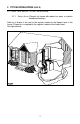
2. TYPICAL INSTALLATIONS (CONT’D) 2.1 HEPA 1000 2.1.1 AND HF 1.0 UNIT INSTALLATIONS STAND ALONE (Primarily for homes with radiant hot water or electric baseboard heating.) Stale air is drawn to the unit by the register located at the highest level of the house. Filtered air is supplied by the register located at the lowest level. See figure below.
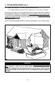
2. TYPICAL INSTALLATIONS (CONT’D) 2.1 HEPA 1000 AND HF 1.0 UNIT INSTALLATIONS (CONT’D) 2.1.2 CENTRAL DRAW POINT (CONNECTION TO FORCED AIR SYSTEM) Stale air is drawn to the unit by the register located at the highest level of the house. Filtered air is supplied to the return (plenum) of the forced air unit. For this type of installation, it is not essential that the forced air system blower runs when the unit is in operation, but we recommend it. See figure below.
2. TYPICAL INSTALLATIONS (CONT’D) 2.1 HEPA 1000 AND HF 1.0 UNIT INSTALLATIONS (CONT’D) 2.1.3 RETURN-RETURN INSTALLATION (CONNECTION TO A FORCED AIR SYSTEM) Filtered air and stale air flow through the forced air system ducts which simplifies the installation. Filtered air is supplied to the return (plenum) of the forced air unit. To avoid cross-contamination and achieve highest efficiencies, the forced air system blower must always be ON (or the unit efficiency will be affected). See figure below.
2. TYPICAL INSTALLATIONS (CONT’D) 2.2 INSTALLATION FOR HEPA 4000 ONLY 2.2.1 GEOGRAPHICAL LOCATION The HEPA 4000 unit was created to meet specific requirements related to geographic locations. Take a look on the map below. The shaded area shows where the HEPA 4000 can be installed. HELENA OLYMPIA BISMARCK ST.
2. TYPICAL INSTALLATIONS (CONT’D) 2.2 INSTALLATION FOR HEPA 4000 ONLY (CONT’D) 2.2.2 HEPA 4000 ATTIC INSTALLATION All 3 types of installation can be used in the attic (Stand Alone, Central Draw Point or Return-Return). The example shown below is a Return-Return installation (connection to a forced air system). CAUTION Due to the potential temperature difference between the attic and the rest of the house, all unit ducts must be insulated. CAUTION The attic temperature must always be above 0°C (32°F).
2. TYPICAL INSTALLATIONS (CONT’D) 2.3 HEPA 2000, HF 2.0, HEPA 3000, HF 3.0 UNIT INSTALLATIONS 2.3.1 AND HEPA 4000 STAND ALONE (Primarily for homes with radiant hot water or electric baseboard heating.) A portion of stale air (coming from the register located at the highest level of the house) is exhausted to the outside and the rest is drawn to the unit. Outside fresh air is blended with interior air and then filtered. Fresh filtered air is supplied by the register located in the lowest livable level.
2. TYPICAL INSTALLATIONS (CONT’D) 2.3 HEPA 2000, HF 2.0, HEPA 3000, HF 3.0 INSTALLATIONS (CONT’D) 2.3.2 CENTRAL DRAW POINT (CONNECTION TO AND HEPA 4000 UNIT A FORCED AIR SYSTEM) A portion of stale air (coming from the register located in the highest level of the house) is exhausted to the outside and the rest is drawn to the unit. Outside fresh air is blended with interior air and then filtered. This filtered air is supplied to the return (plenum) of the forced air unit.
2. TYPICAL INSTALLATIONS (CONT’D) 2.3 HEPA 2000, HF 2.0, HEPA 3000, HF 3.0 INSTALLATIONS (CONT’D) AND 2.3.3 RETURN-TO-RETURN INSTALLATION (CONNECTION TO HEPA 4000 UNIT A FORCED AIR SYSTEM) A portion of stale air is exhausted to the outside and the rest is drawn to the unit. Outside fresh air is blended with interior air and then filtered. This filtered air is supplied to the return (plenum) of the forced air unit.
3. DIMENSIONS 3.1 HEPA 1000 AND HF 1.0 UNITS 29'' (737 mm) 17.8'' (452 mm) 22.9'' (581 mm) VK0047 FRONT VIEW TOP VIEW 3.2 HEPA 2000, HF 2.0, HEPA 3000, HF 3.0 AND HEPA 4000 UNITS 29.4'' (748 mm) 17.8'' (452 mm) 22.
3. DIMENSIONS (CONT’D) 3.3 MOUNTING • AND SERVICING CONSIDERATIONS The two following pictures are showing the minimum clearance needed to open the door completely. 8” (203 mm) 22” (559 mm) 22.5” (572 mm) 15.75” (400 mm) VD0117 VD0116 NOTE: A minimum of 8” (203 mm) clearance from any obstruction on top of the unit is required for the ductwork radius turn. • The joist opening needed to install the Tandem® tansition must be 9 3/4” (248 mm) minimum.
4. INSTALL THE UNIT 4.1 LOCATING AND MOUNTING THE UNIT Choose an appropriate location for the unit. • Within an area of the house where the ambiant temperature is between 10°C (50°F) and 65°C (149°F) (basement, furnace room, closet, etc.). • So as to provide easy access to the interior of the unit, for filter maintenance. • Close to an exterior wall, so as to limit the length of the insulated flexible duct to and from the unit (not necessary for HEPA 1000 and HF 1.0 units).
4. INSTALL THE UNIT (CONT’D) 4.3 HOW TO HANG THE UNIT Use the 4 chains and springs in the hardware pack provided with the unit. According to your needs, you can install the unit either in vertical or horizontal position. VERTICAL POSITION - ALL MODELS VD0074 HORIZONTAL POSITION (LEFT ALL MODELS HORIZONTAL POSITION (RIGHT SIDE) MODELS HEPA 1000, HF 1.0 HEPA 2000, HF 2.
4. INSTALL THE UNIT (CONT’D) 4.3 HOW TO HANG THE UNIT (CONT’D) • Turn the switch knob to OFF position in order to unlock the door. Unlatch the door and open it. Using a screwdriver, remove the 2 retaining screws of the front plate and carefully remove the front plate from the unit. VO0019 • Insert the 4 hooks in the square holes and fix them to the unit using 4 screws #8 - 32 x 3/4”. NOTE: If an optional wall controll has to be installed, go to Section 5.0 on pages 29 to 31.
4. INSTALL THE UNIT (CONT’D) 4.5 INSTALLING 8’’ DUCTS AND REGISTERS 4.5.1 STAND ALONE SYSTEM (AS ILLUSTRATED IN SECTIONS 2.1.1 AND 2.3.1) Stale air exhaust ductwork ! WARNING Never install a stale air exhaust register in a closed room where a combustion device operates, such as a gas furnace, a gas water heater or a fireplace. 0 • Install the stale air exhaust register in the main area where the contaminants are produced: kitchen, living room, etc.
4. INSTALL THE UNIT (CONT’D) 4.5 INSTALLING 8’’ DUCTS AND REGISTERS (CONT’D) How to connect the 8’’ flexible duct to the registers and unit ports (cont’d) • Using the colored sticker dot included, identify which duct it is (red dot for stale airflow and blue dot for filtered airflow). Repeat the procedure for the other register. • Each port is identified on top of the unit (see illustrations below).
4. INSTALL THE UNIT (CONT’D) 4.5 INSTALLING 8’’ DUCTS AND REGISTERS (CONT’D) 4.5.2 CENTRAL DRAW POINT (AS ILLUSTRATED IN SECTIONS 2.1.2 AND 2.3.2) (CONT’D) Filtered air ductwork (Return side connection) (cont’d) • Fix the duct connector to the forced air unit duct using its 4 retaining screws (#8 x 3/4” long). Seal with duct tape. • Take one end of the 8’’ flexible duct and slide it over the duct connector. Secure with a tie wrap. Carefully seal the connection with duct tape.
4. INSTALL THE UNIT (CONT’D) 4.6 INSTALLING INSULATED FLEXIBLE DUCTS (HEPA 2000, HF2.0, HEPA 3000, HF 3.0 AND HEPA 4000 UNITS ONLY) CAUTION Make sure the vapor barrier on the insulated ducts does not tear during installation. Use the following procedure for connecting the insulated flexible ducts to the Tandem® transition* (EXHAUST AIR TO OUTSIDE and FRESH AIR FROM OUTSIDE).
4. INSTALL THE UNIT (CONT’D) 4.6 INSTALLING INSULATED FLEXIBLE DUCTS (HEPA 2000, HF 2.0, HEPA 3000, HF 3.0 AND HEPA 4000 UNITS ONLY) (CONT’D) 4.6.2 CONNECTION TO THE 5’’ TO 6’’ OVAL PORTS OF THE UNIT Use the following procedure for connecting the insulated flexible ducts to the 5’’ to 6’’ oval ports of the unit (EXHAUST AIR TO OUTSIDE and FRESH AIR FROM OUTSIDE). 1. Pull back the insulation to expose the flexible duct. VJ0016 2.
4. INSTALL THE UNIT (CONT’D) 4.7 INSTALLING DUAL EXTERIOR HOOD* (HEPA 2000, HF 2.0, HEPA 3000, HF 3.0 AND HEPA 4000 UNITS ONLY) 4.7.1 ASSEMBLING DUAL EXTERIOR HOOD Exterior dual hood is coming in separate parts. Using 2 #8 x 3/4” screws, assemble the top metal screen and the plastic grille to the dual exterior hood. Then, slide the bottom metal screen to the dual exterior hood. See illustration beside. VO0024 *Patent pending 4.7.
4. INSTALL THE UNIT (CONT’D) 4.7 INSTALLING DUAL EXTERIOR HOOD (HEPA 2000, HF 2.0, HEPA 3000, HF 3.0 AND HEPA 4000 UNITS ONLY) (CONT’D) 4.7.3 CONNECTING TANDEM® TRANSITION TO EXTERIOR DUAL HOOD (CONT’D) 2. Joint the end of the Tandem® transition to the rear of the exterior backplate. Secure with 2 Xmas tree pins and seal properly with duct tape. Xmas tree pin VD0085 CAUTION The exterior backplate must be installed with the word ‘’TOP’’ pointing upward. 3.
4. INSTALL THE UNIT (CONT’D) 4.8 CONNECTING THE DRAIN (HEPA 3000 AND HF 3.0 UNITS ONLY) 1 2 3 1 1 VO0025 VO0046 1.Remove the door by turning the switch knob to the OFF position (to unlock the door).Then, unlatch the door and open it. Slide out the core assembly to access the 2 drain fitting hole locations (1). Punch out the holes. 2 2.Hand tighten the 2 plastic drain fittings (1) using the gaskets (2) and nuts (3) as shown. Close the door. 27'' 686 mm 7'' (178 mm) VO0027 3 4 VO0028 3.
5. CONTROLS 5.1 MAIN SWITCH All units are equipped with a 3-position main switch, located on the front panel. NORMAL/REMOTE: UNIT IS OPERATING ON NORMAL SPEED. THIS IS THE RIGHT POSITION WHEN AN OPTIONAL OFF: UNIT WALL CONTROL IS USED. IS OFF AND DOOR IS UNLOCKED. BOOST: UNIT IS OPERATING ON HIGH SPEED. VC0053 5.2 OPTIONAL WALL CONTROLS There are 2 optional wall controls available: C12 / CM control (intented for HEPA 1000 / HF 1.0 and HEPA 2000 / HF 2.
5. CONTROLS (CONT’D) 5.4 INSTALLATION OF THE OPTIONAL WALL CONTROLS (CONTROLS C12 / CM AND C34 / CMR) ! WARNING Always disconnect the unit before making any connections. Failure in disconnecting power could result in electrical shock or damage of the wall control or electronic module inside the unit. 0 CAUTION Never install more than one optional wall control per unit. 1.Determine the more convenient location for the control. 2 2.Remove the cover plate control (1).
5. CONTROLS (CONT’D) 5.4 INSTALLATION OF THE OPTIONAL WALL CONTROLS (CONTROLS C12 / CM AND C34 / CMR) (CONT’D) 5. Pass the other end of the cable through the wall. Reinstall the cover plate.Using wall anchors (not included) and provided screws, mount the wall control on the wall. See illustrations below. 3 2 2 1 4 3 1 5 4 VC0051 1) Wall anchors 2) Control cable 3) Control backplate VC0052 4) Control 5) Screws 1) Outlet box 2) Control cable 3) Control 4) Screws 6. Route the cable to the unit.
5. CONTROLS (CONT’D) 5.4 INSTALLATION OF THE OPTIONAL WALL CONTROLS (CONTROLS C12 / CM AND C34 / CMR) (CONT’D) 8. Using a small rod, pierce a hole through the unit at the end of the wire channel. (See picture beside.) Splice back the end of the cable to access the 4 wires. Remove the insulated sleeve of each wire ends. Insert the end of the cable through the unit, using the small hole previously done. VD0088 9.
5. CONTROLS (CONT’D) 5.5 OPERATING C12 / CM CONTROL 5.5.1 C12 / CM CONTROL POWER DESCRIPTION INDICATOR: BOOST: LIGHTS UP WHEN SLIDE SWITCH IS ON NORMAL OR UNIT BOOST HIGH SPEED. POSITION. FILTER IS OPERATING ON NORMAL: MAINTENANCE UNIT INDICATOR: IS OPERATING ON NORMAL SPEED. FLASHES EVERY MINUTE TO INDICATE IT IS ON DUTY. FLASHES EVERY SECOND WHEN OFF: UNIT IS OFF. ITS TIME TO REPLACE PREFILTER. SEE BIANNUAL MAINTENANCE IN SECTION 6.
5. CONTROLS (CONT’D) 5.6 OPERATING C34 / CMR CONTROL 5.6.1 C34 / CMR CONTROL FRESH DESCRIPTION RECIRCULATION AIR INDICATOR: LIGHTS UP WHEN SLIDE SWITCH IS ON OR BOOST INDICATOR: LIGHTS UP WHEN SLIDE SWITCH IS ON NORMAL RECIRCULATION. UNIT POSITION. IS OPERATING ON NORMAL FILTER SPEED. MAINTENANCE INDICATOR: BOOST FLASHES WHEN IT IS TIME TO REPLACE PREFILTER SWITCH IS ON AND WASH CORE FILTERS. SEE BIANNUAL MAINTENANCE IN SECTION 6. INDICATOR: LIGHTS UP WHEN SLIDE BOOST POSITION.
6. MAINTENANCE ! WARNING Risk of electrical shocks. Before performing any maintenance or servicing, always disconnect the unit from its power source. 0 6.1 BIANNUAL MAINTENANCE (ESSENTIAL) If your unit is equipped with an optionnal wall control (C12 / CM or C34 / CMR) you should perform this maintenance when the Filter Maintenance light is flashing. Otherwise, this maintenance must be performed every 6 months to ensure your unit proper operation for years to come. Follow these steps: 1.
6. MAINTENANCE (CONT’D) 6.1 BIANNUAL MAINTENANCE (ESSENTIAL) (CONT’D) 4. Using your thumbs, push on the prefilter* side to disengage it from the filter cartridge. Then, slide it out of the filter cartridge and discard it. Install the new prefilter* by reversing this operation. 1 2 VD0092 VD0093 1) Filter cartridge 2) Prefilter NOTE: If you are using a washable foam filter (MERV 8), vacuum to remove most of the dust. Let it soak in a solution of warm water and mild soap.
6. MAINTENANCE (CONT’D) 6.1 BIANNUAL MAINTENANCE (ESSENTIAL) (CONT’D) 6. 7. Close the door, close the latches and turn ON the switch knob to its previous position. If your unit is equipped with an optionnal wall control (C12 / CM) or C34 / CMR), reset the filter maintenance indicator by inserting a small rod (eg: paper clip end) into the reset filter hole of the optional wall control. Press lightly until the Filter Maintenance indicator light turns off. 6.
7. PARTS ORDERING CHART No. Description 1 2 3 4 5 6 7 Prefilter Kit (2) HEPA Pleated Filter Kit MERV 12 Filter Kit* Foam Filter MERV 8 Kit* Core Filter Kit (2) Single Exterior Hood Kit** Wall Control C12** No. Description 1 2 3 4 5A 5B 6 7 Prefilter Kit (2) HEPA Pleated Filter Kit MERV 12 Filter Kit* Foam Filter MERV 8 Kit* Core Filter Kit (2) Core Filter Kit (2) Single Exterior Hood Kit** Wall Control C34** Part Number 05123 04803 04804 04852 05120 13940 04862 HEPA 1000 HEPA 2000 HF 1.0 HF 2.
8. TROUBLESHOOTING PROBLEMS SOLUTIONS 1.Unit does not start at Normal or Boost position. 2. Unit does not run at Normal speed, but runs at Boost. 3. Unit is not operating as per the selected mode. 4. Wall control indicators do not work properly or not at all. 5. On C34 / CMR wall control only, 1 or 2 light indicators are flashing every second. • Check breaker or fuse in main distribution panel. • Check there is 120V at the electrical outlet.