INSTALLATION INSTRUCTIONS HRV90H AND ERV90HC Model no.: HRV90HT (HRV with ports on top) VB0082 Model no.: HRV90HS (HRV with ports on sides) VB0081 Model no.: ERV90HCT (ERV with ports on top) VB0080 Model no.: ERV90HCS (ERV with ports on sides) VB0079 RESIDENTIAL USE ONLY READ AND SAVE THESE INSTRUCTIONS 06010C rev.
ABOUT THIS MANUAL Because of the large amount of models covered by this publication, the illustrations are typical ones. Some details of your unit may be slightly different than the ones shown. Please take note that this manual uses the following symbols to emphasize particular information: ! WARNING Identifies an instruction which, if not followed, might cause serious personal injuries including possibility of death.
TABLE OF CONTENTS 1.0 1.1 1.2 1.3 1.4 1.5 1.6 2.0 2.1 2.2 2.3 2.4 3.0 3.1 3.2 3.3 3.4 3.5 3.6 3.7 3.8 3.9 4.0 4.1 4.2 4.3 4.4 5.0 6.0 7.0 8.0 9.0 9.1 9.2 10.0 11.0 TECHNICAL DATA . . . . . . . . . . . . . . . . . . . . . . . . . . . . . . . . . . . . . . . . . . . . . . . . . . . . . . . . . .4-6 AIR DISTRIBUTION (NORMAL OPERATION) . . . . . . . . . . . . . . . . . . . . . . . . . . . . . . . . . . . . . . . . . . . . . . . . . . . . .4 AIR DISTRIBUTION (RECIRCULATION OR DEFROST MODE) . . . . . . . .
1. TECHNICAL DATA 1.1 AIR DISTRIBUTION (NORMAL OPERATION) HRV EXHAUST ERV AIR- FRESH FROM BUILDING FRESH EXHAUST AIR FROM BUILDING EXHAUST TO BUILDING FRESH AIR TO BUILDING FRESH AIR FROM OUTSIDE AIR AIR EXHAUST VF0039 1.
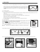
1. TECHNICAL DATA (CONT’D) 1.4 PERFORMANCE CHARTS 1.4.1 HRV UNITS Energy Performance Ventilation Performance EXT STATIC PRESSURE Pa in.w.g. 25 .1 50 .2 75 .3 100 .4 125 .5 150 .6 175 .7 200 .
1. TECHNICAL DATA (CONT’D) 1.5 DIMENSIONS 1.5.1 DIMENSIONS FOR PORTS ON SIDES UNITS HRV 27 1 16” (688 mm) 22 9 16” (574 mm) 4’’ (102 mm) 1913 16” (503 mm) 12 3 16” (310 mm) 13¾” (349 mm) 6’’ (152 mm) 2” (51 mm) VK0055 ERV 27 1 16” (688 mm) 22 9 16” (574 mm) 4’’ (102 mm) 1913 16” (503 mm) 12 3 16” (310 mm) 6’’ (152 mm) 2” (51 mm) VK0057 1.5.
2. TYPICAL INSTALLATIONS Installations may vary according to the type of unit and the ports configuration (top or sides). Use the following illustrations as guidelines to help you decide on how the unit will be installed. All the units should be hung from the joists. In every case, bathroom fans and a range hood should be used to exhaust stale air. Also, for homes with more than one level, we recommend one exhaust register at the highest level.
2. TYPICAL INSTALLATIONS (CONT’D) 2.4 INSTALLATION FOR ERV UNITS ONLY 2.4.1 GEOGRAPHICAL LOCATION The ERV units are created to meet specific requirements related to geographical locations. Take a look at the map below; the shaded area shows the limits where the ERV unit can be installed. However, there is no geographical limitation for installing an HRV unit.
3. INSTALLATION 3.1 INSPECT THE CONTENTS OF THE BOX • Inspect the exterior of the unit for shipping damage. Ensure that there is no damage to the door, door latches, power cord, etc. • Remove and discard the 2 transport brackets (A) and open the door. Discard the styrofoam A fillers (ERV units only) and remove the hardware kit from the unit. Inspect the interior of the unit for damage. Ensure that heat or energy recovery core, core filters, insulation, dampers, etc. are all intact. VD0183 3.
3. INSTALLATION (CONT’D) 3.4 HOW TO HANG THE UNIT Hang the unit with the 4 chains, hooks and springs provided. VD0185 VD0184 CAUTION Make sure the unit is level. 3.5 PLANNING OF THE DUCTWORK • Keep it simple. Plan for a minimum of bends and joints. • Keep the length of insulated ducts to a minimum. • Do not ventilate crawl spaces or cold rooms. Do not attempt to recover the exhaust air from a dryer or a range hood. This would cause clogging of the filters and recovery module.
3. INSTALLATION (CONT’D) 3.6 INSTALLING THE DUCTWORK AND REGISTERS (CONT’D) 3.6.2 CENTRAL DRAW POINT SYSTEM (AS ILLUSTRATED IN SECTION 2.2) Stale air exhaust ductwork Same as for Fully Ducted System, described on point 3.6.1. Fresh air distribution ductwork ! WARNING When performing duct connections, always use approved tools and materials. Respect all corresponding laws and safety regulations. Please refer to your local building code.
3. INSTALLATION (CONT’D) 3.6 INSTALLING THE DUCTWORK AND 3.6.3 SIMPLIFIED INSTALLATION (AS REGISTERS (CONT’D) ILLUSTRATED IN SECTION 2.3) ! WARNING When performing duct connections, always use approved tools and materials. Respect all corresponding laws and/or safety regulations. Please refer to your local building code.
3. INSTALLATION (CONT’D) 3.7 CONNECTING THE DUCTS TO THE UNIT Insulated flexible ducts Use the following procedure for connecting the insulated flexible ducts to the port of the unit (Exhaust air to outside and Fresh air from outside ports). CAUTION Make sure the balancing dampers are set to their appropriate position before connecting the ducts to the ports. See Section 3.3. VJ0039 Pull back the insulation to expose the flexible duct.
3. INSTALLATION (CONT’D) 3.8 INSTALLING THE TANDEM® TRANSITION KIT (CONT’D) 3.8.1 1. 2. 3. 4. CONNECTION TO TANDEM® TRANSITION For each duct, pull back the insulation to expose the interior flexible duct. Connect the interior flexible duct to the smaller part of the Tandem® transition (5’’ oval) using a tie wrap. Pull the insulation over the joint. Pull the vapor barrier over the insulation. Apply duct tape gently to the joint in order to make an airtight seal. See figures below.
3. INSTALLATION (CONT’D) 3.8 INSTALLING THE TANDEM® TRANSITION KIT (CONT’D) 3.8.4 CONNECTING TANDEM® TRANSITION TO THE DUAL EXTERIOR HOOD (CONT’D) Xmas tree pin 2. Join the end of the Tandem® transition to the rear of the exterior backplate. Secure with 2 Xmas tree pins and seal properly with duct tape. VD0085 CAUTION The exterior backplate must be installed with the word «TOP» pointing upward. 3. Using 4 #8 x 11¼2” screws, mount the the exterior backplate to the exterior wall.
3. INSTALLATION (CONT’D) 3.9 INSTALLING 2 EXTERIOR HOODS Choose an appropriate location to install the exterior hoods: • There must be a minimum distance of 6 feet (1.8 m) between the hoods to avoid cross-contamination • There must be a minimum distance of 18 inches (457 mm) from the ground Make sure the intake hood is at least 6 feet (1.
4. CONTROLS 4.1 INTEGRATED CONTROL WARNING AVERTISSEMENT Risk of electric shock. Before performing any maintenance or servicing, always disconnect the unit from its power source. Danger d’électrocution. Débranchez toujours l’appareil avant d’entreprendre des travaux d’entretien ou de réparation. CAUTION ATTENTION Unscrew both screws to open the electrical Dévisser les deux vis pour ouvrir le compartiment compartment. To completely remove, detach électrique.
4. CONTROLS (CONT’D) 4.2 ELECTRICAL CONNECTION TO OPTIONAL WALL CONTROLS (CONT’D) 4.2.1 ELECTRICAL CONNECTION TO VT4W MAIN WALL CONTROL M MAIN AIN WALLWALL CONTROL LITE-TOUCH BRONZE andVT4W CONTROL NO C NC I OC OL Y R G B Y SIMPLE TOUCH BRONZE REAR REARVIEW VIEW OC G B G B VE0101A 4.2.
4. CONTROLS (CONT’D) 4.4 OPTIONAL AUXILIARY WALL CONTROLS OPERATION 4.4.1 20-MINUTE LIGHTED PUSH-BUTTON TIMER ON Set the push-button timer to ON. The fan motors will then operate at high speed for 20 minutes and the indicator will light up. To stop activation, push one time; the unit will then get back to previous selection. VC0084 4.4.2 60-MINUTE CRANK TIMER TURN PAST 20 OFF 10 20 This control makes the system operate at high speed for periods varying from 10 to 60 minutes. 30 60 40 50 VC0017 4.
- 20 - VE0130A Supply fan M2 motor Supply fan motor C2 capacitor Exhaust fan motor C1 capacitor Exhaust fan motor M1 G BN BN BL BL J2 12 54321 2 1 1 2 3 1 2 3 2 1 J9 J8 54321 F1 W1 W G BK J10 12 J12 J11 See note 6 BN 4 321 See note 1 2 1 120 V, 60 Hz J4 J6 J7 J5 Y J3 J1 R1 COLOR CODE BK BLACK BL BLUE BN BROWN G GREEN R RED W WHITE Y YELLOW nc no connection Critical characteristic.
7. BALANCING THE UNIT To avoid balancing, the difference between stale air ducts total lenght and fresh air ducts total lenght must not exceed 50 ft. However, even if the stale air ducts and fresh air ducts lenghts are almost equal, your local building codes may require balancing the unit. If the unit does not need to be balanced, shut all the pressure taps (located on the unit door) with the small plastic plugs included in the hardware kit. 7.
8. CONNECTING THE DRAIN (HRV UNITS ONLY) A VD0181 From the inner side of the unit door, using the provided drain tube, punch out both drain holes (A). VO0091 In order to keep the drain pan intact, hand tighten the 2 plastic drain fittings to the unit door using the gaskets and nuts as shown. Tie-wrap VO0092 VO0093 Cut 2 sections of plastic tubing, about 12” (305 mm) long and attach them to each drain fitting. Join the 2 short sections to the «T» junction and main tube as shown.
9. MAINTENANCE ! WARNING Risk of electrical shocks. Before performing any maintenance or servicing, always disconnect the unit from its power source. Since this guide covers both HRV and ERV units, top and side ports, the illustrations shown in the maintenance procedures are typical. The following procedures applies for both HRV and ERV units. Refer to pictures below to identify the inner parts of your unit.
9. MAINTENANCE (CONT’D) 9.1 SEMI-ANNUAL MAINTENANCE (CONT’D) 4. Clean the inside walls of the unit with a clean damp cloth, then wipe with a clean dry one. 5. Wash the 2 core filters under hot water with mild soap. Rinse thoroughly and let dry completely before reinstalling on the core. 6. Remove the dust on the core using a vacuum cleaner and a soft brush attachment.
10. SERVICE PARTS 13 12 1 3 2 4 11 5 7 6 10 4 3 9 8 VL0019 ITEM DESCRIPTION 1 2 3 4 OVAL PORT (FITS 5” DIAMETER DUCTS) DOOR LATCH WITH SCREWS OVAL PORT WITH INTEGRATED BALANCING DAMPER MOTOR & WHEEL ASS’Y (MOTOR CAPACITOR INCLUDED) CAPACITOR 5 µF 5* CAPACITOR 7.
11. TROUBLESHOOTING If the integrated control LED of the unit is flashing, this means the unit sensors detected a problem. See the table below to know where on the unit the problem occurs. LED flashes GREEN. • Thermistor error. Replace the entire port assembly (fresh air from outside port). LED flashes AMBER. • Damper error. Go to Point 6. LED flashes RED. • The door is open and the unit is not unplugged. Close the door and press once on the integrated control push button to reset the unit.