
Installation Guide
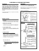

INSTALLATION
1. WARNING
To avoid fire or electrical shock, turn off power at circuit
breaker or fuse. Test that the power is off before wiring.
2. MOUNT THE SWITCH BOX
Install at least a 2-1/2" deep switch box for 14 gauge wire
or at least a 2-3/4" deep switch box for 12 gauge wire.
3. ATTACH POWER CABLE
Connect cables to switch box and appliance using
appropriate connectors. Provide 6" leads inside box and
appliance.
4. CONNECT WIRING
General instructions for all configurations:
Remove insulation per strip gauge on control (approxi-
mately 1/2") and insert SOLID COPPER WIRE ONLY
into appropriate holes (BLACK (line hot) TO COMMON
TERMINAL” HOLE). Make sure both the switch box and
the appliance are properly grounded.
Choose 4A., 4B. or 4C
4A. When using 2-Rocker or 3-Rocker Switch to turn
an appliance ON & OFF:
Make electrical connections following appropriate
diagram.
(over)
WARNING
To prevent serious injury from electrical shock or damage
to electrical components -
DO NOT WIRE HOT!
Each individual rocker switch on this control is rated at 15
AMPS, @ 120 VAC. The total load on this control must not
exceed 20 AMPS, @ 120 VAC.
Warranty is void if miswired.
WARNING
ALL ELECTRICAL WORK MUST BE DONE IN ACCOR-
DANCE WITH LOCAL CODES, ORDINANCES, OR NA-
TIONAL ELECTRICAL CODE AS APPLICABLE. FOR
SAFETY, THIS PRODUCT MUST BE INSTALLED IN A
GROUNDED SWITCH BOX. IF YOU ARE UNFAMILIAR
WITH METHODS OF INSTALLING ELECTRICAL WIR-
ING, SECURE THE SERVICES OF A QUALIFIED ELEC-
TRICIAN.
Turn off power and lock out service panel before installing
or wiring this product.
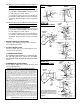
2-ROCKER & 3-ROCKER SWITCHES
3 - ROCKER SWITCH
* CODE REQUIRES BOTH ENDS OF THIS WIRE'S INSULATION
TO BE COLORED BLACK, SINCE IT IS SWITCHED. USE A
FELT TIPPED MARKER.
2 - ROCKER SWITCH
STEP 4A
NOTE: If the switch has not been wired properly and wires need
to be moved, proceed as follows:
WARNING: To avoid fire or electrical shock, turn off power at
circuit breaker or fuse. Test that the power is off
before wiring.
1. Each wire opening has a
release slot.
2. Push a small nail or screw-
driver into release slot
while gently removing wire.
3. DO NOT pull any wire out
of the switch without using
the release slot. The
switch may become dam-
aged.
RELEASE SLOT
WIRE OPENING