
Installation Instructions


INSTALLATION, USE & CARE INSTRUCTIONS
INSTALLATION
5
INSTALL THE POWER MODULE
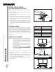
1. Remove the grease filter by pushing down on its latch tab
and tilting the filter downward (Fig. 5). Set aside the filter.
2. Remove the damper and the parts bag taped inside the
power module.
3. Disassemble the electrical cover (grey part in Fig. 6) from
inside the power module by removing both its retaining
screws. Slide the cover toward the blower in order to
disengage its hook (shown in dotted line in inset) from
the power module wall. Set aside the cover along with its
screws.
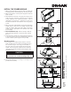
4. Run house power cable between service panel and power
module location. Stub out a 2-foot length of power cable
inside the cabinet. Attach the power cable to the power
module using an appropriate 7/8” diameter strain relief
(not included).
5. Ducted installation only: Slide the damper inside the
blower discharge opening on top of the power module
(Fig. 7).
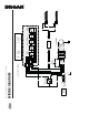
6. Insert the power module in the cabinet (Fig. 8) and secure
to the wood blocks previously installed using (4) wood
screws included in parts bag (2 screws per side).
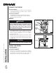
Alternate mounting:
7. For installation in a cabinet without bottom, insert the
power module in the liner. Install 2 wood blocks having
2½” minimum height x 10¼” long (not included), on
top of the liner and on left and right side of the power
module. Secure the power module to the wood blocks
using (4) wood screws included in parts bag (2 screws
per side) (Fig. 9).
CAUTION
Ensure the wood blocks rest completely on the
top of the liner, not on the liner flanges (Fig. 10)
NOTE: Liner apearance may vary.
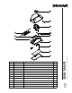
8. Secure the liner (Fig. 11) using 4 mounting screws
(included with the liner).
SCREWS
FIG. 5
FIG. 6
HOOK
FIG. 7
DAMPER
CABINET INSIDE VIEW
FIG. 8
FIG. 9
LINER
LINER WITH
POWER MODULE
FIG. 11
YES NO
FIG. 10