
Installation Instructions


INSTALLATION, USE & CARE INSTRUCTIONS
INSTALLATION
6
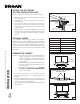
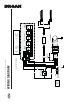
CONNECT DUCTWORK
Ducted Installation
Use 6” round metal duct to connect the blower discharge
to the ductwork above. Use metal foil tape to make all
joints secure and air tight.
Non-Ducted Installation
The 360NDK non-duct kit is required for this type of
installation (purchase separately). To install, follow the
intructions packed with this kit.
WIRING
WARNING
Risk of electric shock. Electrical wiring must be
done by qualified personnel in accordance with all
applicable codes and standards. Before connecting
wires, switch power off at service panel and lock
service disconnecting means to prevent power from
being switched on accidentally.
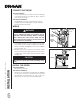
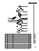
1. Using appropriate wire nuts (not included), connect house
power cable to power module wiring: BLACK to BLACK,
WHITE to WHITE and GREEN or bare wire to GREEN
ground wire (Fig. 12).
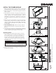
2. Reinstall wiring cover and attach it to the power module
using its retaining screws (Fig. 9). Ensure its hook (shown
in dotted line in inset) is well inserted in the power module
wall (Fig. 13).
CAUTION
Take care not to pinch wires while reinstalling wiring
cover.
INSTALL THE FILTER
Ducted Installation
Reinstall the grease filter.
Non-Ducted Installation
Attach the non-ducted filter (included with the 360NDK
non-duct kit) to the back of the grease filter using clips
(provided with non-ducted filter). To order a new non-
ducted filter, use service part number S99010464.
!
FIG. 12
WHITE WIRE
BLACK
WIRE
FIG. 13
HOOK
GREEN
GROUND
WIRE
HOUSE
POWER
CABLE
SCREWS