
Install Instructions

English
MODEL RD4
RADIATION DAMPER
INSTALLATION INSTRUCTIONS
For Use In 1, 2 or 3 Hour Rated Floor-Ceiling and Roof-Ceiling
Designs
Horizontal Mount Only
For Use With The Following Fan Models:
Fan Models
Broan HD50, HD80, 676, 684
NuTone HD50NT, HD80NT, 676NT, 684NT
1. Plan installation so that ceiling penetration is located within
ceiling tiles or panels without necessitating cuts in any ceiling
suspension main runners or cross tees. If required, a maximum
of one runner or cross tee may be cut to accommodate desired
damper location. Cut ends must be supported by a minimum
12 steel wire gauge (3mm) vertical hanger wire.
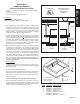
2. Position radiation damper on the inlet side of the fan so that the
arrow in the damper will point UP in the nished installation.
Attach the damper to the fan using #8 (M4) sheet metal screws
(provided). There must be a minimum of two connections on each
of two opposite sides. Care must be taken to ensure that the
fasteners do not interfere with the closing of the damper curtain.
For best results, use mounting holes provided.
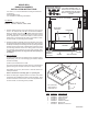
3. Mount fan/damper assembly to the deck or ceiling structure above
or adjacent to the assembly. If the assembly is hung from the
structure above, a minimum 12 steel wire gauge (3mm) hanger
wire must be used. There must be a minimum of two wires on
each of two opposite sides. If the assembly is directly mounted
to the adjacent structure, use #8 (M4) sheet metal screws or
1/4” (6mm) diameter bolts with nuts to mechanically fasten it
to the structure. Position fan/damper assembly so that the inlet
face of the radiation damper is ush with the nished surface of
the ceiling. Ceiling opening must be no larger than the inlet
opening of the damper.
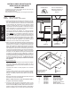
4. New Construction
A housing mask has been provided to keep construction dust,
drywall spray, paint, etc. from damaging the radiation damper
of blower assembly.
a) Bend up the small tab of the mask.
b) Tuck the opposite side of the mask under one of the damper’s
grille mounting ears and push mask up into damper housing.
Note: Mask can be put in place before or after the blowers as-
sembly is installed.
Remove mask before installing grille or operating fan.
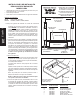
5. Attach the metal grille, supplied, over the inlet face of the radia-
tion damper using #8 (M4) sheet metal screws (provided). There
must be a minimum of one screw on each of two opposite sides.
For best results, use mounting holes provided.
1
2
3
4
ITEM PART NO. DESCRIPTION
1 99523579 Fusible Link
2 99260485 Sheet Metal Nut
3 99170245 Damper Screw
4 99150573 Grille Screw
5 99523357 Radiation Damper
-- 98009908 Metal Grille
-- 97015727 Metal Duct Connector
For replacement
parts telephone
1-800-558-1711
99043769A
CLASSIFIED
SEE DETAILS ON UL
CLASSIFICATION
MARKING ON
PRODUCT
FAN
GRILLE
WIRE
DAMPER
GRILLE
SCREW
CEILING
MOUNTING
BRACKET
5