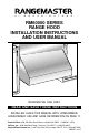
B Y B R O A N - N U T O N E RM60000 SERIES RANGE HOOD INSTALLATION INSTRUCTIONS AND USER MANUAL HB0026 RESIDENTIAL USE ONLY READ AND SAVE THESE INSTRUCTIONS INSTALLER: LEAVE THIS MANUAL WITH HOMEOWNER. HOMEOWNER: USE AND CARE INFORMATION ON PAGE 11. Broan-NuTone LLC, 926 West State Street, Hartford, WI 53027 (1-800-637-1453) NuTone, Inc., 4820 Red Bank Road, Cincinnati, OH 45227 (1-800-543-8687) Broan-NuTone Canada, Inc.
! WARNING ! TO REDUCE THE RISK OF FIRE, ELECTRIC SHOCK, OR INJURY TO PERSON(S) OBSERVE THE FOLLOWING: 1. 2. 3. 4. 5. 6. 7. 8. 9. Use this unit only in the manner intended by the manufacturer. If you have questions, contact the manufacturer at the address or telephone number listed in the warranty. Before servicing or cleaning unit, switch power off at service panel and lock service disconnecting means to prevent power from being switched on accidentally.
TABLE OF CONTENTS 1.0 2.0 3.0 4.0 5.0 6.0 7.0 8.0 9.0 10.0 11.0 12.0 13.0 14.0 15.0 16.0 17.0 SELECT BLOWER OPTION AND INSTALL DUCTWORK . .5 MEASURE INSTALLATION . . . . . . . . . . . . . . . . . . . . . . . . .6 PREPARE THE INSTALLATION . . . . . . . . . . . . . . . . . . . . . .6 INSTALL BACKSPLASH . . . . . . . . . . . . . . . . . . . . . . . . . . .7 INSTALL WOOD MOUNTING STRIP . . . . . . . . . . . . . . . . . .7 INSTALL THE HOOD . . . . . . . . . . . . . . . . . . . . . . . . . . . . .
Wall & Roof Caps, Ext. Blowers MODEL 331H MODEL 335 MODEL 437 MODEL 441 (600 cfm) OR (1200 cfm) OR (High Capacity (10” Rd. 332H (900 cfm) 336 (1500 cfm) Wall Cap) Roof Cap) (Exterior Blower) (Exterior Blower) MODEL 647 (7” Rd. Wall Cap) MODEL 634 OR 644 (Roof Cap) Elbows & In-Line Dampers MODEL 418 (10” Rd. Adjustable Elbow) MODEL 421 (10” Rd. Vert. In-Line Damper) MODEL 415 (7” Rd. Adjustable Elbow) Ductwork MODEL 407 (7” Rd. Duct - 2 ft. sections) MODEL 410 (10” Rd. Duct - 2 ft.
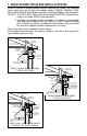
1. SELECT BLOWER OPTION AND INSTALL DUCTWORK Either an interior or exterior blower may be used with this hood. The RM60000 Series hood must be installed with blower models RM325H, RM326H, 331H, 332H, 335 or 336 only. Other blowers cannot be substituted. (Blowers sold separately). NOTES:1. The 331H, 332H, 335 or 336 exterior blower MUST BE installed with the rough-in kit model 332KR (sold separately). 2.
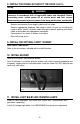
2. MEASURE INSTALLATION Dimensions for the most common installations are shown below. Adjust your measurements for various heights of ceilings, soffits, cabinets or cooktops. For proper operation, the hood must be a minimum of 24" and a maximum of 30" above the cooktop. Standard 8 ft. (2.
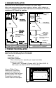
4. INSTALL BACKSPLASH (OPTIONAL) RMP Series Backsplash must be installed before the hood shell because the hood shell covers the backsplash top mounting screws. In order to be able to install the backsplash, make sure you have at least 18” (457 mm) clearance between bottom of hood and range control panel or cooktop. (Refer to instructions included with backsplash.) 5.
7. INSTALL TRANSITION TO ROUGH-IN PLATE Model 423, 424, 427, 453, or 454 Attach transition (if required) to blower rough-in plate. Use duct tape to make all joints secure and air-tight. NOTE: Model RM325H blower plate connects directly to 7" round ductwork without a transition. Exterior blower models utilize a model 332KR rough-in plate which connects directly to 10” round ductwork without a transition. HD0049 8. INSTALL THE ROUGH-IN PLATE TO THE HOOD Run power cable to installation location.
8. INSTALL THE ROUGH-IN PLATE TO THE HOOD (CONT’D) Wiring 0 ! WARNING Risk of electrical shock. Electrical wiring must be done by qualified personnel in accordance with all applicable codes and standards. Before connecting wires, switch power off at service panel and lock service disconnecting means to prevent power from being switched on accidentally. Remove wiring cover from rough-in plate and set aside. Remove appropriate knockout from rough-in plate.
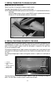
12. INSTALL FILTERS CAUTION Remove protective plastic film covering filters before installing them. It is recommended to install side filters first and finish with center one(s). 1. Insert upper end of filter into the hood (finger sized cup side). 2. Raise lower end toward the inside of hood. 3. Position rear part of filter into channel and pull. 4. Using finger sized cup, pull on the upper end of filter and slide it under the front inner retaining piece.
13. USE AND CARE Grease Filters The grease filters should be cleaned frequently. Use a warm detergent solution. Grease filters are dishwasher safe. Wash more often if our cooking style generates greater grease - like frying foods or wok cooking. Remove filters by pushing filters towards the back of hood and rotating filters downward. Blower Cleaning Remove the filters in order to access the blower. Vacuum blower to clean. Do not immerse in water. Refer to blower instruction manual for more details.
14. OPERATION Always turn ON your hood before you begin cooking in order to establish an air flow in the kitchen. Let the blower run for a few minutes to clear the air after you turn off the range. This will help keep the whole kitchen cleaner and brighter. 4 6 5 3 1 3 1 3 2 HC0004 1. Warming lamps 2. Warming lamp switches 3. Halogen lights 4. Halogen light switches 5. ON/OFF Blower switch 6.
15.
16.
16. SERVICE PARTS (CONT’D) KEY NO.
17. WARRANTY BROAN-NUTONE ONE YEAR LIMITED WARRANTY Broan-NuTone warrants to the original consumer purchaser of its products that such products will be free from defects in materials or workmanship for a period of one year from the date of original purchase. THERE ARE NO OTHER WARRANTIES, EXPRESS OR IMPLIED, INCLUDING, BUT NOT LIMITED TO, IMPLIED WARRANTIES OR MERCHANTABILITY OR FITNESS FOR A PARTICULAR PURPOSE.
B Y B R O A N - N U T O N E GUIDE D’INSTALLATION ET D’UTILISATION DES HOTTES DE CUISINIÈRE SÉRIE RM60000 HB0026 USAGE RÉSIDENTIEL SEULEMENT LIRE ET CONSERVER CES INSTRUCTIONS INSTALLATEUR : LAISSER CE GUIDE AU PROPRIÉTAIRE. PROPRIÉTAIRE : INSTRUCTIONS D’UTILISATION ET D’ENTRETIEN EN PAGE 27. Broan-NuTone LLC, 926 West State Street, Hartford, WI 53027 (1-800-637-1453) NuTone, Inc., 4820 Red Bank Road, Cincinnati, OH 45227 (1-800-543-8687) Broan-NuTone Canada, Inc.
! AVERTISSEMENT ! AVERTISSEMENT AFIN DE RÉDUIRE LES RISQUES D’INCENDIE, D’ÉLECTROCUTION OU DE BLESSURES CORPORELLES, SUIVEZ LES INSTRUCTIONS SUIVANTES : 1. 2. 3. 4. 5. 6. 7. 8. 9. N’utilisez cet appareil que de la façon prévue par le manufacturier. Si vous avez des questions, contactez le manufacturier à l’adresse et au numéro de téléphone indiqués sur la garantie.
TABLE DES MATIÈRES 1.0 2.0 3.0 4.0 5.0 6.0 7.0 8.0 9.0 10.0 11.0 12.0 13.0 14.0 15.0 16.0 17.0 CHOISIR L’OPTION VENTILATEUR ET INSTALLER LES CONDUITS . . . . . . . . . . . . . . . . . . .21 MESURER L’INSTALLATION . . . . . . . . . . . . . . . . . . . . . .22 PRÉPARER L’INSTALLATION . . . . . . . . . . . . . . . . . . . . . .22 INSTALLER LE DOSSERET . . . . . . . . . . . . . . . . . . . . . . .23 INSTALLER LA LISIÈRE DE BOIS . . . . . . . . . . . . . . . . . .23 INSTALLER LA HOTTE . . . . . . . . . . . . .
Capuchons de mur ou toit, Ventilateurs ext. MODÈLE 331H (600 pcm) OU 332H (900 pcm) (Ventilateur ext.) MODÈLE 335 MODÈLE 437 MODÈLE 441 MODÈLE 647 (1200 pcm) OU (capuchon de (capuchon de (capuchon de 336 (1500 pcm) toit à haute toit 10” rond) mur 7” rond) (Ventilateur ext.
1. CHOISIR L’OPTION VENTILATEUR ET INSTALLER LES CONDUITS La hotte de cuisinière Série RM60000 fonctionne autant avec un ventilateur extérieur qu’intérieur. Elle doit être installée uniquement avec un des ventilateurs suivants : RM325H, RM326H, 331H, 332H, 335 ou 336 (vendus séparément). Aucun autre ventilateur ne doit être utilisé. NOTES : 1. Le ventilateur extérieur 331H, 332H, 335 ou 336 DOIT être installé avec la plaque ventilateur modèle 332KR (vendue séparément). 2.
2. MESURER L’INSTALLATION Les dimensions pour les installations les plus courantes sont indiquées plus bas. Ajustez vos mesures pour les différentes hauteurs de plafond, soffite, armoires ou surfaces de cuisson. Afin d'assurer un meilleur fonctionnement, la hotte doit être à un minimum de 24" (610 mm) et à un maximum de 30" (762 mm) au-dessus de la surface de cuisson.
4. INSTALLER LE DOSSERET (Facultatif) Série RMP Le dosseret doit être installé avant la hotte puisque celle-ci couvre les vis d’installation du dosseret. Afin de pouvoir installer le dosseret, s’assurer d’avoir au moins 18” (457 mm) entre le dessus de la hotte et le panneau de contrôle de la cuisinière ou de la surface de cuisson (Voir les instructions fournies avec le dosseret.) 5.
7. INSTALLER LA TRANSITION À LA PLAQUE VENTILATEUR Modèles 423, 424, 427, 453 ou 454 Fixer la transition (si requise) à la plaque ventilateur. Sceller tous les joints avec du ruban à conduits. NOTE : La plaque ventilateur du modèle RM325H à un ventilateur se branche directement à un conduit rond de 7", sans transition. Les ventilateurs extérieurs utilisent la plaque ventilateur 332KR; elle se branche directement à un conduit rond de 10", sans transition. HD0049 8.
8. INSTALLER LA PLAQUE VENTILATEUR SUR LA HOTTE (SUITE) Branchements électriques 0 ! AVERTISSEMENT Risque de chocs électriques. Le raccordement électrique doit être effectué par du personnel qualifié conformément aux codes et standards. Avant d’effectuer le branchement, coupez l’alimentation électrique au panneau de service et verrouillez-le pour éviter une mise en marche accidentelle. Retirer le couvercle du boîtier électrique de la plaque ventilateur et mettre de côté.
12. INSTALLER LES FILTRES ATTENTION Retirer le film de plastique protecteur des filtres avant de les installer. Il est recommandé d’installer d’abord les filtres situés aux extrémités et de terminer par le(s) filtre(s) du centre. 1. Insérer la partie supérieure du filtre dans la hotte (côté de la poignée). 2. Faire pivoter la partie inférieure vers l’intérieur de la hotte. 3. Placer le filtre sous l’attache située au fond de la hotte. 4.
13. ENTRETIEN Filtres Les filtres doivent être nettoyés fréquemment. Utiliser une solution d’eau chaude et de détergent. Les filtres sont lavables au lave-vaisselle.Les filtres doivent être lavés plus souvent si vos habitudes de cuisson génèrent plus de graisse - comme par exemple de la friture ou des aliments sautés au wok. Pour retirer les filtres, pousser chaque filtre vers le bas en utilisant la poignée afin des dégager de la pièce de retenue. Puis, pousser vers l’intérieur de la hotte et les retirer.
14. FONCTIONNEMENT Toujours mettre en marche la hotte avant de commencer la cuisson afin d’établir une circulation d’air dans la cuisine. Aussi, laisser la hotte fonctionner quelques minutes après l’arrêt de la cuisinière afin de nettoyer l’air. Ceci aidera à garder la cuisine plus propre et plus claire. 4 6 5 3 3 1 1 3 2 HC0004 1. Lampes réchauds 2. Interrupteurs de lampes réchauds 3. La mpes halogènes 4. Interrupteurs de la mpes halogènes 5. Interrupteur Marche/Arrêt du ventilateur 6.
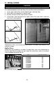
15. SCHÉMA ÉLECTRIQUE INTER. LAMPE CHAUF. DROITE COURANT N 120V 60HZ B VERS MOTEUR DOUILLE LAMPE CHAUF. DROITE N N N B V THERMOSTAT HS B INTER. VENTILATEUR N CONTRÔLE DE N VITESSE PRISE NEMA 5-15P DOUILLE AMPOULE DROITE B N B N INTERRUPTEURS D’ÉCLAIRAGE N DOUILLE AMPOULE CENTRALE B N DOUILLE AMPOULE GAUCHE N INTER. LAMPE N CHAUF. GAUCHE B DOUILLE LAMPE CHAUF.
16.
16. PIÈCES DE REMPLACEMENT (SUITE) NO.DE REF. 1 2 3 4 5 6 7 8 9 10 11 12 ‡ ‡ ‡ 13 14 15 16 17 17 17 17 18 18 18 18 18 18 18 18 19 20 21 22 ‡ ‡ ‡ ‡* NO.
17. GARANTIE GARANTIE LIMITÉE D’UN AN DE BROAN-NUTONE Broan-NuTone garantit à l’acheteur consommateur initial de ses produits qu’ils sont exempts de tous défauts dans les matières premières ou la main-d’œuvre pour une période d’un an à compter de la date d’achat par le consommateur initial. IL N’Y A PAS D’AUTRES GARANTIES, EXPRIMÉES OU IMPLICITES, INCLUANT, MAIS NON LIMITÉES AUX GARANTIES IMPLICITES POUR FIN DE COMMERCIALISATION ET DE CONVENANCE DANS UN BUT PARTICULIER.
B Y B R O A N - N U T O N E MANUAL DE INSTALACIÓN Y UTILIZACIÓN DE LAS CAMPANAS SERIE RM60000 HB0026 USO DOMÉSTICO SOLAMENTE LEER Y CONSERVAR ESTAS INSTRUCCIONES INSTALADOR: DEJAR ESTE MANUAL AL PROPRIETARIO PROPRIETARIO: INSTRUCCIONES DE UTILIZACIÓN Y MANTENIMIENTO EN LA PÁGINA 44 Broan-NuTone LLC, 926 West State Street, Hartford, WI 53027 (1-800-637-1453) NuTone, Inc., 4820 Red Bank Road, Cincinnati, OH 45227 (1-800-543-8687) Broan-NuTone Canada, Inc.
! AVERTENCIA ! AVERTENCIA PARA REDUCIR EL RIESGO DE INCENDIO, DESCARGA ELÉCTRICA, O LESIONES A PERSONAS, CUMPLA LOS SIGUIENTES PUNTOS : PARA EVITAR RIESGO DE LESIONES PERSONALES EN CASO DE INCENDIO DE GRASA EN LA SUPERFICIE DE LA ESTUFA, OBSERVE LO SIGUIENTE*: 1. 1. 2. 3. 4. 5. 6. 7. 8. 9. Solamente use esta unidad de la manera propuesta por el fabricante. Si tiene alguna pregunta, communiquese con el fabricante en la dirección o teléfono anotados en la garantía.
ÌNDICE DE MATERIAS 1.0 2.0 3.0 4.0 5.0 6.0 7.0 8.0 9.0 10.0 11.0 12.0 13.0 14.0 15.0 16.0 17.0 SELECCIONE LA OPTION VENTILADOR Y INSTALE LOS CONDUCTOS . . . . . . . . . . . . .37 MIDA LA INSTALACIÓN . . . . . . . . . . . . . . . . . .38 PREPARE LA INSTALACIÓN . . . . . . . . . . . . . .38 INSTALE LA PLACA PARA SALPICADURAS . .39 INSTALACIÓN DE LA TIRA DE MADERA . . . . .39 INSTALE LA CAMPANA . . . . . . . . . . . . . . . . . .39 INSTALE LA TRANSICIÓN EN PLACA DEL VENTILADOR . . . . . . . . . . . . .
Tapas del muro o techo Ventiladors ext MODELO 331H (600 pcm) O 332H (900 pcm) (Ventilador ext.) MODELO 335 MODELO 437 MODELO 441 MODELO 647 (Tapa de (tapa de muro (1200 pcm) O (Tapa de 336 (1500 pcm) techo de alta techo redondo redondo 7”) 10” (Ventilador ext.
1. SELECCIONE LA OPTION VENTILADOR Y INSTALE LOS CONDUCTOS La campana Serie RM60000 funciona tanto con un ventilador exterior como interior. Esta campana debe ser instalada con ventilador modelo RM325H, RM326H, 331H, 332H, 335 o 336 solamente. Otros ventiladores no pueden reemplazar a este ventiladores. NOTAS: 1. El ventilador exterior 331H, 332H, 335 o 336 debe ser instalado con la placa del ventilador modelo 332KR (vendida separadamente). 2.
2. MIDA LA INSTALACIÓN A continuación se muestran las dimensiones para las instalaciones más comunes. Ajuste sus medidas para las diversas alturas de techos, intradós, gabinetes o superficies para cocinar. Para lograr un funcionamiento adecuado, la parte inferior de la campana deberá estar entre 610 y 762 mm (24 y 30 pulg.) sobre el nivel de la superficie para cocinar.
4. INSTALE LA PLACA PARA SALPICADURAS (OPCIONAL) La placa para salpicaduras se debe instalar antes que la campana debido a que este cubre los tornillos de montaje de la placa para salpicaduras. Para instalar la placa para salpicaduras,asegúrese de tener 18” (457 mm) entre debajo de la campana y el panel de control de la cocina o encima de la cocina (Vea las instrucciones incluidas con la placa para salpicaduras.) 5.
7. INSTALE LA TRANSICIÔN EN LA PLACA DEL VENTILADOR Modelos 423, 424, 427, 453, o 454 Monte la transición en la placa del ventilador. Use cinta para ductos para que todas las juntas sean seguras y herméticas. NOTA: La placa de un solo ventilador del modelo RM325H se conecta directamente al conducto redondo de 7", sin transición. Los ventiladores exterior usan el modelo de la placa del ventilador 332KR que se conecta directamente al conducto redondo de 10”, sin transición. HD0049 8.
8. INSTALE LA PLACA DEL VENTILADOR EN LA CAMPANA (CONTINUACIÒN) Conecciòn eléctrica ! AVERTENCIA Peligro de choque eléctrico. La instalación eléctrica debe ser hecha por personal calificado de acuerdo con todos los códigos aplicables y normas. Antes de efectuar el empalme, cortar la alimentación eléctrica del interruptor y cerrar con securidad para prevenir una alimentación accidental. 0 Retire la cubierta del cableado de la placa del ventilador y poner a un lado..
12. INSTALE LOS FILTROS PRECAUCIÓN Antes de la instalación, sacar las peliculas de plastico sobre los filtros. Es recomandable de instalar los filtros de lado en primer yde terminar con el o los filtro(s) del centro. 1. Insertar la parte superior del filtro en la campana (al lado de la palangana). 2. Acer girar la parte inferior hacia el interior de la campana. 3. Instale el filtro debajo el atadero y tire. 4. Empleando la palangana, resbale el filtro debajo la pieza de reteniendo interior.
13. MANTENIMIENT0 Filtros Los filtros deben limpiarse con frecuencia. Utilice agua caliente con un detergente suave. Los filtros pueden ponerse en el lavavajillas. Limpie más seguido si su comida crea mucho grasa - como fritura o preparar la comida con wok. Empuje los filtros hacia el interior de la campana y liberelos de la pieza de reteniendo para que en seguida los retire de la campana. Limpieza del ventilador Quitar los filtros a fin que tener acceso al ventilador.
14. FUNCIONAMIENTO Siempre hacer funcionar la campana antes de comenzar a cocinar a fin de establecer una circulación de aire en la cocina. Deje igualmente funcionar la campana algunos minutos después de que pare de cocinar a fin de limpiar el aire. Esto ayuda a concervar la cocina mas limpia y un aire puro. 4 6 5 3 1 3 1 3 2 HC0004 1. Lámparas termógena 2. Interruptores de lámpara termógena 3. Luces halógena 4. Interruptores de luces halógena 5. Interruptor Encender/Apagar del ventilador 6.
15. ESQUEMA ELÉCTRICO INTER. LAMPARA TERMÓGENA. DERECHA N 120V 60HZ B HACIA MOTOR CASQUILLO LAMP. TERM. DERECHA N N N B V THERMOSTATO HS CONTROL DE N VELOCIDAD ENCHUFE NEMA B INTER. VENTILADOR N CASQUILLO BOMBILLA DER. 5-15P B N B N INTERRUPTORES DE LUZ N CASQUILLO BOMBILLA CENT. B N CASQUILLO BOMBILLA. IZQ N INTER. LAMP. N TERM. IZQ. CASQUILLO LAMP. TERM. IZQ.
16.
16. REPUESTOS (CONTINUACIÒN) NO.DE REF. 1 2 3 4 5 6 7 8 9 10 11 12 ‡ ‡ ‡ 13 14 15 16 17 17 17 17 18 18 18 18 18 18 18 18 19 20 21 22 ‡ ‡ ‡ ‡* NO.
17. GARANTIA GARANTÍA BROAN-NUTONE LIMITADA POR UN AÑO Broan-NuTone garantiza al consumidor comprador original de sus productos que dichos productos carecerán de defectos en materiales o en mano de obra por un período de un año a partir de la fecha original de compra. NO EXISTEN OTRAS GARANTÍAS, EXPRESAS O IMPLÍCITAS, INCLUYENDO, PERO NO LIMITADAS A, GARANTÍAS IMPLÍCITAS DE COMERCIALIZACIÓN O ACTITUD PARA UN PROPOSITO PARTICULAR.