
Technical data


Web Tools Administrator’s Guide 149
53-1002934-02
Displaying switch information
10
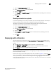
The detailed fan status for the switch displays, as shown in Figure 28.
Viewing the temperature status
The icon on the Temp button indicates the overall status of the temperature. For more information
regarding switch temperature, refer to the appropriate hardware documentation.
To view the temperature status, perform the following steps.
1. Select a logical switch from the Logical Switch list in the top-right corner of the Switch Explorer
window.
The selected switch displays in the Switch View. The icon on the Temp button indicates the
overall status of the temperature.
2. Click Temp on the Switch View.
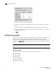
The detailed temperature sensor states for the switch are displayed, as shown in Figure 27.
Viewing the power supply status
The icon on the Power button indicates the overall status of the power supply status. For more
information regarding switch power modules, refer to the appropriate hardware documentation.
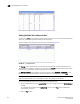
FIGURE 29 Power States window
To view the power supply status, perform the following steps.
1. Select a logical switch from the Logical Switch list in the top-right corner of the Switch Explorer
window.
2. The selected switch displays in the Switch View. The icon on the Power button indicates the
overall status of the power supply.
3. Click Power on the Switch View. The detailed power supply states are displayed (Figure 29). If
you are using the Brocade 6510 or Brocade 6520, the Type column displays either AC or DC.
For all other hardware the value will be N/A.
Checking the physical health of a switch
The Status button displays the operational state of the switch. The icon on the button displays the
real-time status of the switch.