
Technical data


242 Web Tools Administrator’s Guide
53-1002934-02
LLDP-DCBX configuration
18
10. In the FC0E Priority Bits field, enter a value that indicates the desired user priority. Each bit
represents a user priority associated with FCoE traffic.
The range of valid values is from 0 through 255. The default is 8.
Even though setting multiple bits is allowed (exercising the full range of values), it doesn't
make sense to set more than one bit, because adapters don't support multiple priorities for
FCoE.
NOTE
Web Tools accepts only decimal values for this option, but the CLI allows only entries in list
format or hexadecimal. For example, if you enter the value 8 (decimal) in Web Tools, CLI
represents it as 3 in list format. If you enter the value 255 (decimal) in Web Tools, CLI
represents it as 0 1 2 3 4 5 6 7 in list format.
11. Select the parameters you want to exchange.
Note that the term TLV indicates packaging of parameters into a Brocade-specific
Type/Length/Value (TLV):
• Advertise Optional-tlv—Advertises the following optional TLVs:
- system-description—Describes switch or blade characteristics.
- port-description—Describes the configured port.
- system-name—Specifies the system name.
- system-capabilities—Describes the system capabilities.
- management-address—The IP address of the management port.
• Advertise dot1-tlv—Select this check box to advertise to any attached device to send IEEE
802.1 LLDP type, length, and values.
• Advertise dot3-tlv—Select this check box to advertise to any attached device to send IEEE
802.3 LLDP type, length, and values.
• Advertise DCBx-tlv—Select this check box to advertise to any attached device the
respective LLDP type, length, and values.
• Advertise DCBx-fcoe-logical-link—Select this check box to advertise to any attached device
to send DCBX protocol over LLDP to negotiate the logical link type, length, and values.
• Advertise DCBx-fcoe-app—Select this check box to advertise application type, length, and
values to ensure interoperability of traffic over DCBX protocol running over LLDP.
12. Click Apply.
13. Click Save Configuration.
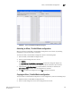
Adding an LLDP profile
The LLDP profile determines LLDP settings per port.
To add an LLDP profile, perform the following steps.
1. Select the DCB tab on the Switch Administration window.
2. Select the LLDP-DCBX tab.
3. Select the LLDP Profile tab.
4. Click Add.