
Technical data

Brocade SilkWorm 4100 Hardware Reference Manual A-7
Publication Number: 53-0000563-02
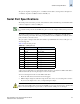
Serial Port Specifications
A
The ports are capable of operating at 1, 2, or 4 Gbit/sec and are able to autonegotiate to the higher of 1
or 2 Gbit/sec. Operation at 4 Gbit/sec must be manually set.
Serial Port Specifications
The serial port is located on the port side of the switch. It is a three-wire RS-232 port with a DB-9 male
connector, designed to connect to a DTE port.
The serial port can be used to connect to a computer workstation to configure the switch IP address
without connecting to the fabric. The serial port’s parameters are fixed at 9600 baud, 8 data bits, and no
parity, with flow control set to None.
The port requires a straight serial cable with a female 9-pin subminiature-D connector. Only pins 2, 3,
and 5 are supported.
Table A-6 lists the cable pinouts.
A 10 ft. (3.0 m) serial cable is provided with the switch. It can be converted from a DB-9 serial cable to
an RJ-45 serial cable by removing the adapter on the end of the cable.
To remove the adapter from the end of the DB-9 serial cable:
1. Ensure the cable and both screws have been disengaged.
2. Pull the adapter straight out, without moving it from side to side, to loosen seating of the connector.
If you move the adapter side to side, you might damage the adapter.
Note
To protect the serial port from dust and ESD, keep the cover on the serial port whenever the port is not in
use.
Table A-6 Cabling Pinouts
PIN Signal Description
1 Not supported Not supported
2 RxData Receive data
3 TxData Transmit data
4 Not supported Not supported
5 GND Logic ground
6 Not supported Not supported
7 Not supported Not supported
8 Not supported Not supported
9 Not supported Not supported
Caution
When removing the DB-9 male connector from the DTE port, do not use excessive force; otherwise the
DB-9 connector will split into two parts easily so that the switch’s DTE port is not damaged.