
Technical data


12-6 Web Tools Administrator’s Guide
Publication Number: 53-0000522-09
Configuring CUP Port Connectivity
12
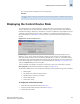
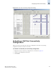
The FICON CUP tabbed page displays, with the FICON Management Server subtabbed page in
front (see Figure 12-1 on page 12-2). All attributes on this tab are read-only until FMS Mode is
enabled.
The Control Device state is displayed as neutral or switched in the Control Device Allegiance field.
If FMS mode is enabled, and the Control Device state is unavailable, the FICON CUP Busy Error
is displayed. Click Reset Allegiance in the error message to reset the Control Device state to its
correct state (see Figure 12-2).
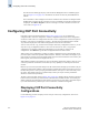
Configuring CUP Port Connectivity
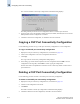
In the Port Connectivity subpanel (shown in Figure 12-3 on page 12-7), you can manage the
configuration files and active configuration. All CUP configuration files and the active configuration
are listed in a table. The active configuration is listed as “Active Configuration*” and the description in
the table is “Current active configuration on switch.” The other special configuration file is the IPL.
Any other files displayed are user-defined configurations and are stored on the switch.
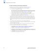
You can create, activate, copy, or delete saved CUP port connectivity configurations; however, you can
only edit or copy a configuration while it is active.You can also activate, edit, or copy the IPL
configuration. You must have FMS mode enabled before you can make any changes to the
configurations. Click Refresh to get the latest configuration file list from the switch.
When creating a new configuration or editing an existing configuration, keep in mind that Web Tools
port name input is restricted to printable ASCII characters. Therefore, when Web Tools displays a port
name, if there are characters beyond printable ASCII characters (which would have been created by the
Host Program), those characters are displayed as dots (.).
When initially installed, a switch allows any port to dynamically communicate with any other port. Two
connectivity attributes are defined to restrict this any-to-any capability for external ports: Block and
Prohibit.
Block is a port connectivity attribute that prevents all communication through a port. Prohibit is the port
connectivity attribute that prohibits or allows dynamic communication between ports when a port is not
blocked. Each port has a vector specifying its Prohibit attribute with respect to each of the other ports in
the switch. This attribute is always set symmetrically in that a pair of ports is either prohibited or
allowed to communicate dynamically.
The Port Connectivity table (shown in Figure 12-4 on page 12-9) displays the Port number (in physical-
location format), Port Name (port address name), Block attribute, Prohibit attribute, and Area Id (port
address, displayed in hexadecimal) in fixed columns. The right side is a port matrix, which lists all ports
by Area ID and identifies prohibited ports. Those columns are scrollable and swappable.
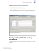
Displaying CUP Port Connectivity
Configurations
Use the following procedure to display a list of CUP port connectivity configurations, as shown in
Figure 12-3 on page 12-7.