SilkWorm 4100 QuickStart Guide Supporting Fabric OS v4.4.
Copyright © 2003-2004, Brocade Communications Systems, Incorporated. ALL RIGHTS RESERVED. Publication Number: 53-0000564-01 Brocade, the Brocade B weave logo, Secure Fabric OS, and SilkWorm are registered trademarks of Brocade Communications Systems, Inc., in the United States and/or in other countries. FICON is a registered trademark of IBM Corporation in the U.S. and other countries.
This QuickStart guide is intended as an overview to help experienced installers unpack, install, and configure a SilkWorm 4100 switch quickly. For detailed installation and configuration instructions, refer to the SilkWorm 4100 Hardware Reference Manual. You can install the SilkWorm 4100 in the following ways: • • As a standalone unit on a flat surface, as described in this document. • In an EIA cabinet using the Slide Rack Mount Kit (optional).
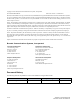
Time and Items Required Table 1 lists the main installation tasks for the SilkWorm 4100 switch and the estimated time required . These time estimates assume a prepared installation site and appropriate power and network connectivity.
Verify that the ambient air temperature does not exceed 40° Celsius (104° Fahrenheit) and that the ambient humidity remains between 20 percent and 85 percent while the switch is operating. If installing the switch in a cabinet: • • The cabinet must be a standard EIA cabinet. • Ground all equipment in the cabinet through a reliable branch circuit connection and maintain ground at all times. Do not rely on a secondary connection to a branch circuit, such as a power strip.
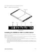
Figure 1 displays the port-side view of the SilkWorm 4100 switch.
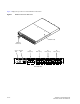
Figure 2 displays the nonport side view of the SilkWorm 4100 switch. Figure 2 SilkWorm 4100 Nonport Side View SilkWorm 4100 Scale: 1/8" = 1" Power Supply 2 Fan 3 Fan 2 Fan 1 Power Supply 1 Nonport Side View Installing the SilkWorm 4100 in an EIA Cabinet Refer to the Fixed Rack Mount Kit Installation Procedure that shipped with your unit for instructions on installing the SilkWorm 4100 in a fixed rack.
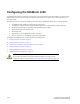
Configuring the SilkWorm 4100 The SilkWorm 4100 must be configured correctly before it can operate within a network and fabric. For instructions on configuring the switch to operate in a fabric containing switches from other vendors, refer to the Brocade Fabric OS Procedures Guide.
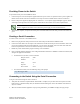
Providing Power to the Switch To provide electrical power to the SilkWorm 4100: 1. Connect the power cords to both power supplies and then to power sources on separate circuits to protect against AC failure. Ensure that the cords have a minimum service loop of 6 inches available and are routed to avoid stress. 2. Power on the power supplies by flipping both AC switches to “1”. The power supply LED lights up green, and the switch begins running POST.
Setting the Switch IP Address To replace the default IP address and related information: 1. Enter the ipAddrSet command at the terminal emulator application prompt, and enter the requested information at the prompts: switch:admin> ipaddrset Ethernet IP Address [10.77.77.77]:10.32.53.47 Ethernet Subnetmask [255.0.0.0]:255.255.240.0 Fibre Channel IP Address [0.0.0.0]: Fibre Channel Subnetmask [0.0.0.0]: Gateway IP Address [0.0.0.0]:10.32.48.
a. Disable the switch by typing the switchDisable command. b. Enter the configure command. The command prompts display sequentially; enter a new value or press Enter to accept each default value. c. Enter y after the “Fabric parameters” prompt: Fabric parameters (yes, y, no, n): [no] y d. Enter a unique domain ID (such as the domain ID used by the previous switch, if still available): Domain: (1..239) [1] 3 3. 4. e.
a. Orient a cable connector so that the key (the ridge on one side of connector) aligns with the slot in the transceiver. Then, insert the cable into the transceiver until the latching mechanism clicks. For instructions specific to cable type, refer to the cable manufacturer’s documentation. Note The cable connectors are keyed to ensure correct orientation. If a transceiver does not install easily, ensure that it is correctly oriented. b. Repeat Step a for the remaining transceivers as required. 6.