
Technical data
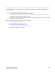
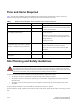
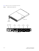
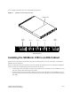
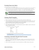
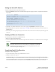
Table Of Contents
SilkWorm 4100 QuickStart Guide 7 of 12
Publication Number: 53-0000564-01
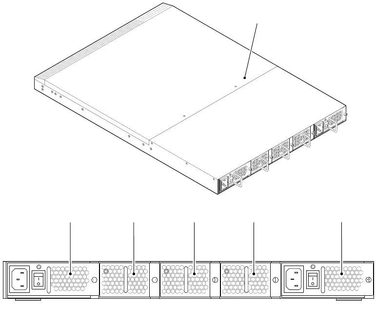
Figure 2 displays the nonport side view of the SilkWorm 4100 switch.
Figure 2 SilkWorm 4100 Nonport Side View
Installing the SilkWorm 4100 in an EIA Cabinet
Refer to the Fixed Rack Mount Kit Installation Procedure that shipped with your unit for instructions on installing the
SilkWorm 4100 in a fixed rack.
Refer to the Slide Rack Mount Kit Installation Procedure (optional) for detailed instructions on installing the SilkWorm
4100. The switch can be installed using the slide rack mount kit in two ways:
• To allow the port side of the switch to slide out of the exhaust-air side of the cabinet. In this installation, the port
side of the switch is flush with the edge of the cabinet.
• To allow the nonport side of the switch to slide out the cool-air side of the cabinet. In this installation, the port
side of the switch is set three inches back from the edge of the cabinet, allowing a more gradual bend in the fiber-
optic cables.
Scale: 1/8" = 1"
SilkWorm 4100
Non
p
ortSideView
Power
Supply 2
Power
Supply 1
Fan 3 Fan 2 Fan 1