Publication Number: 53-1000424-03 Publication Date: March, 2008 Brocade 5000 Hardware Reference Manual Supporting Fabric OS v5.
Copyright © 2008 Brocade Communications Systems, Inc. All Rights Reserved. Brocade, Fabric OS, File Lifecycle Manager, MyView, and StorageX are registered trademarks and the Brocade B-wing symbol, DCX, and SAN Health are trademarks of Brocade Communications Systems, Inc., in the United States and/or in other countries. All other brands, products, or service names are or may be trademarks or service marks of, and are used to identify, products or services of their respective owners.
Contents About This Document How This Document Is Organized . . . . . . . . . . . . . . . . . . . . . . . . . . . . . . . . . . . . . v Supported Hardware and Software . . . . . . . . . . . . . . . . . . . . . . . . . . . . . . . . . . . . vi What’s New in This Document . . . . . . . . . . . . . . . . . . . . . . . . . . . . . . . . . . . . . . . . vi Document Conventions . . . . . . . . . . . . . . . . . . . . . . . . . . . . . . . . . . . . . . . . . . . . . vi Text Formatting. . . . . . . . . . . . . .
Chapter 3 Operating the Brocade 5000 Powering the Brocade 5000 On and Off . . . . . . . . . . . . . . . . . . . . . . . . . . . . . . . 15 Interpreting LED Activity . . . . . . . . . . . . . . . . . . . . . . . . . . . . . . . . . . . . . . . . . . . . 15 Brocade 5000 LEDs. . . . . . . . . . . . . . . . . . . . . . . . . . . . . . . . . . . . . . . . . . . . 15 Interpreting POST Results. . . . . . . . . . . . . . . . . . . . . . . . . . . . . . . . . . . . . . . . . . . 19 Maintaining the Brocade 5000 . .
About This Document This document is written for network administrators to provide a complete set of Brocade 5000 switch installation procedures and an overview of the switch hardware. This document is specific to the Brocade 5000 switch running Fabric OS v5.2.1.
Supported Hardware and Software Although many different software and hardware configurations are tested and supported by Brocade Communications Systems, Inc. for the Brocade 5000, documenting all possible configurations and scenarios is beyond the scope of this document. What’s New in This Document Minor corrections were made in several chapters. Document Conventions This section describes text formatting conventions and important notices formats.
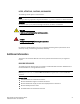
NOTES, ATTENTIONS, CAUTIONS, AND DANGERS The following notices appear in this document. NOTE A note provides a tip, emphasizes important information, or provides a reference to related information. ATTENTION An attention alerts you to potential damage to firmware, hardware, and software. CAUTION A caution alerts you to potential injury to personnel. DANGER A danger alerts you to potential danger to personnel.
Fabric OS • Brocade SilkWorm SAN Glossary • • • • • • • Fabric OS Command Reference Fabric OS Administrator’s Guide Fabric OS MIB Reference Fabric OS Message Reference Fabric Watch Administrator’s Guide Secure Fabric OS Administrator’s Guide Web Tools Administrator’s Guide For practical discussions about SAN design, implementation, and maintenance, you can obtain Building SANs with Brocade Fabric Switches through: http://www.amazon.
Getting Technical Help Contact your switch support supplier for hardware, firmware, and software support, including product repairs and part ordering. To expedite your call, have the following information available: 1.
Document Feedback Because quality is our first concern at Brocade, we have made every effort to ensure the accuracy and completeness of this document. However, if you find an error or an omission, or you think that a topic needs further development, we want to hear from you. Forward your feedback to documentation@brocade.com. Provide the title and version number and as much detail as possible about your issue, including the topic heading and page number and your suggestions for improvement.
Chapter Introducing the Brocade 5000 1 This chapter provides the following information: - “Overview of Brocade 5000,” next “Managing the Brocade 5000” on page 3 “Supported Features” on page 4 Overview of Brocade 5000 The Brocade 5000 switch is a 1U Fibre Channel switch with 32 fixed Fibre Channel SFP ports that supports link speeds up to 1, 2, or 4 Gbit/sec. It includes the Brocade Fabric Operating System and is compatible with the entire Brocade SilkWorm product family.
1 Overview of Brocade 5000 The Brocade 5000 can be mounted in a 1U 19-inch Electronic Industries Association (EIA) rack, with a height of 1U. Because of the shallow depth, no rail kits are required for a rack mount, however the switch can be installed using the fixed or slide rack mount kits. The Brocade 5000 can also be used in a tabletop configuration. Figure 1 shows the port side of the Brocade 5000.
Managing the Brocade 5000 1 FIELD REPLACEABLE UNITS Power supply/fan assembly units are the only Field Replaceable Units (FRUs) in the Brocade 5000. There are two power supply/fan assembly units in the Brocade 5000. They are hot-swappable and redundant, and capable of functioning universally without voltage jumpers or switches. The FRU units are identical and interchangeable. The front panel of the FRUs has a status LED to indicate status of the unit.
1 Supported Features NOTE To achieve in-band support for IP over Fibre Channel, the software must be run on both the HBA and the switch, and it must be supported by both the HBA and HBA driver.
Chapter Installing and Configuring the Brocade 5000 2 This chapter provides the following information: - “Items Included with the Brocade 5000,” next “Installation and Safety Considerations” on page 5 “Setting Up the Switch Using Mounting Ears” on page 6 “Setting Up the Brocade 5000 as a Standalone Unit” on page 7 “Configuring the Brocade 5000” on page 7 “Recommendations for Cable Management” on page 13 Items Included with the Brocade 5000 The following items are included with the standard shipment of
2 Setting Up the Switch Using Mounting Ears - In an EIA cabinet using the mounting ears provided with the switch. This is the recommended installation method. For instructions and more information, refer to “Setting Up the Switch Using Mounting Ears” on page 6. - As a standalone unit on a flat surface. For instructions and more information, refer to “Setting Up the Brocade 5000 as a Standalone Unit” on page 7. - In an EIA cabinet using the Fixed Rack Mount Kit.
Setting Up the Brocade 5000 as a Standalone Unit 2 1. Locate the mounting ear marked “L” for left. 2. Place the long side of the mounting ear against the side of the switch (when facing the port-side of the switch), aligning the holes on the mounting ear to the holes on the side of the switch. 3. Using three of the screws provided in the FRU kit and a screwdriver, attach the mounting ear to the switch. 4. Repeat steps 1 through 3 for the mounting ear marked “R” for right on the right side of the switch.
2 Configuring the Brocade 5000 The following items are required for configuring and connecting the Brocade 5000 for use in a network and fabric: • • The Brocade 5000, installed and connected to a power source A workstation computer that has a terminal emulator application (such as HyperTerminal for Windows) • An unused IP address and corresponding subnet mask and gateway address • The serial cable provided with the switch • An Ethernet cable • SFP transceivers and compatible fibre cables, as required • A
Configuring the Brocade 5000 2 1. Remove the plug from the serial port and insert the serial cable provided with the Brocade 5000. 2. Connect the serial cable to the serial port on the switch and to a serial port on the workstation. 3. Disable any serial communication programs running on the workstation. 4.
2 Configuring the Brocade 5000 4. If the serial port is no longer required, log out of the serial console, remove the serial cable, and replace the plug in the serial port. Creating an Ethernet Connection To create an Ethernet connection to the Brocade 5000: 1. Remove the plug from the Ethernet port. 2. Connect an Ethernet cable to the switch Ethernet port and to the workstation or to an Ethernet network containing the workstation.
Configuring the Brocade 5000 2 3. Install the SFP transceivers in the Fibre Channel ports, as required. The ports selected for use in trunking groups must meet specific requirements. For a list of these requirements, refer to the Brocade Fabric OS Administrator’s Guide. a. Remove the plugs from the ports to be used. b. Position a transceiver so that it is oriented correctly and insert it into a port until it is firmly seated and the latching mechanism clicks.
2 Configuring the Brocade 5000 You should back up the configuration on a regular basis to ensure that a complete configuration is available for downloading to a replacement switch. For specific instructions about how to back up the configuration, refer to the Fabric OS Administrator’s Guide. The switchShow, fabricShow, and configUpload commands are described in detail in the Fabric OS Command Reference. SETTING THE SWITCH DATE AND TIME The date and time switch settings are used for logging events.
Recommendations for Cable Management 2 Example switch:admin> tsclockserver LOCL switch:admin> tsclockserver 132.163.135.131 switch:admin> CORRECTING THE TIME ZONE OF A SWITCH If the time of your switch(es) is off by hours (and not minutes), use the following procedure on all switches to set the time zone: 1. Log in as admin. 2. Enter the tsTimeZone - - interactive command. 3. Follow the prompts to select the correct time zone for the switch.
2 14 Recommendations for Cable Management Brocade 5000 Hardware Reference Manual Publication Number: 53-1000424-03
Chapter Operating the Brocade 5000 3 This chapter provides the following information: - “Powering the Brocade 5000 On and Off,” next “Interpreting LED Activity” on page 15 “Interpreting POST Results” on page 19 “Maintaining the Brocade 5000” on page 19 Powering the Brocade 5000 On and Off To power the Brocade 5000 on, connect one or both power cords to the power connectors on the power supplies and to a power source; then, set the AC power switches to “I”.
3 Interpreting LED Activity Figure 3 shows the locations of the LEDs on the Brocade 5000. FIGURE 3 1 2 3 4 LEDs on Port Side of Brocade 5000 System Status LED Port Status LED System Power LED Power Supply Status LED Table 2 describes the LEDs and their actions on the switch. TABLE 2 Brocade 5000 LED Patterns During Normal Operation LED Name LED Color Status of Hardware Recommended Action Power Supply Status No light Power supply is not receiving power or is off.
Interpreting LED Activity TABLE 2 3 Brocade 5000 LED Patterns During Normal Operation (Continued) LED Name LED Color Status of Hardware Recommended Action System Status No light System is off, boot is not complete, or boot failed. Verify that system is on and has completed booting. Steady green System is on and power supplies are functioning properly. No action required. Steady amber (for more than five seconds) Boot failed, the system is faulty. Perform the following steps: 1.
3 Interpreting LED Activity TABLE 2 18 Brocade 5000 LED Patterns During Normal Operation (Continued) LED Name LED Color Status of Hardware Recommended Action Port Status No light No signal or light carrier (media or cable) detected. Check transceiver and cable. Slow flashing green (flashing in two-second intervals) Port is online but segmented because of a loopback cable or incompatible switch connection. No action required.
Interpreting POST Results 3 Interpreting POST Results POST is a system check that is performed each time the switch is powered on, rebooted, or reset, and during which the LEDs flash different colors. To determine whether POST completed successfully and whether any errors were detected: - Verify that the LEDs on the switch indicate that all components are healthy (LED patterns are described in Table 2 on page 3-16). If one or more LEDs do not display a healthy state: 1.
3 Maintaining the Brocade 5000 For information about specific diagnostic tests, refer to the Brocade Fabric OS Administrator’s Guide. Field Replaceable Units (FRUs) The power supplies have the fans inside and can be replaced onsite without the use of special tools. The power supplies/fan assemblies units are keyed to ensure correct orientation during installation. Replacement instructions are provided with all replacement units ordered. CAUTION The Brocade 5000 has two power cords.
Maintaining the Brocade 5000 - 3 Type the fanShow command at the command prompt to display fan status as shown below: switch:admin> fanshow Fan 1 is OK, speed is 7105 RPM Fan 2 is OK, speed is 7258 RPM Brocade 5000 Hardware Reference Manual Publication Number: 53-1000424-03 21
3 22 Maintaining the Brocade 5000 Brocade 5000 Hardware Reference Manual Publication Number: 53-1000424-03
Appendix Product Specifications 4 This appendix provides the following information: - “Switch Components,” next “Weight and Physical Dimensions” on page 24 “Facility Requirements” on page 24 “Power Supply Specifications” on page 25 “Power Cords (Japan, Denan)” on page 25 “Environmental Requirements” on page 26 “General Specifications” on page 26 “Data Transmission Ranges” on page 27 “Memory Specifications” on page 28 “Fibre Channel Port Specifications” on page 28 “Serial Port Specifications” on page 28
4 Weight and Physical Dimensions Weight and Physical Dimensions Table 3 lists the weight and dimensions of the Brocade 5000. TABLE 3 Physical Specifications Dimension Value Height 1U = 43.5 mm (1.71 inches) Depth 264 mm (10.39 inches) Width 428.75 mm (16.88 inches) Weight (with two power supplies/fan assemblies installed, no SFPs) 10.8 lbs (4.
Power Supply Specifications 4 Power Supply Specifications The power supplies are universal and capable of functioning worldwide without voltage jumpers or switches. They meet IEC 61000-4-5 surge voltage requirements and are autoranging in terms of accommodating input voltages and line frequencies. Each power supply has a built-in fan for cooling, pushing air towards the port side of the switch. Table 4 lists the power supply specifications for the Brocade 5000.
4 Environmental Requirements Environmental Requirements Table 5 lists the acceptable environmental ranges for both operating and non-operating (such as during transportation or storage) conditions.
Data Transmission Ranges TABLE 6 4 General Specifications (Continued) System architecture Nonblocking shared-memory switch System processor PowerPC 440GP, 333 MHz CPU ANSI Fibre Channel protocol FC-PH (Fibre Channel Physical and Signalling Interface standard) Modes of operation Fibre Channel Class 2 and Class 3 Fabric initialization Complies with FC-SW-3 Rev. 6.6 FC-IP (IP over Fibre Channel) Complies with FC-IP 2.
4 Memory Specifications Memory Specifications The Brocade 5000 has three types of memory devices: - Boot flash: 4 MB Compact flash: 1 GB Main memory (SDRAM): 256 MB Fibre Channel Port Specifications The Fibre Channel ports in the Brocade 5000 are compatible with SWL, LWL, and ELWL SFP transceivers. The strength of the signal is determined by the type of transceiver in use. The ports meet all required safety standards.
POST and Boot Specifications TABLE 8 4 Serial Cable Pinouts PIN Signal Description 6 UART1_RXD Receive data 7 Not supported NA 8 Not supported NA POST and Boot Specifications The switch performs POST by default each time it is powered on or rebooted or the system is reset. Boot time with POST is a minimum of three minutes. POST can be skipped after subsequent reboots by entering the fastBoot command. For more information about this command, refer to the Brocade Fabric OS Command Reference.
4 Regulatory Compliance • • • • • • • • • “MIC Statement (Republic of Korea)” on page 30 “VCCI Statement” on page 30 “BSMI Statement (Taiwan)” on page 30 “CE Statement” on page 31 “Canadian Requirements” on page 31 “Laser Compliance” on page 31 “RTC Battery” on page 31 “Electrical Safety” on page 32 “Regulatory Certifications” on page 32 FCC WARNING (US ONLY) This equipment has been tested and complies with the limits for a Class A computing device pursuant to Part 15 of the FCC Rules.
Regulatory Compliance 4 CE STATEMENT ATTENTION This is a Class A product. In a domestic environment, this product might cause radio interference, and the user might be required to take corrective measures.
4 Regulatory Compliance ELECTRICAL SAFETY CAUTION This switch might have more than one power cord. To reduce the risk of electric shock, disconnect both power cords before servicing. CAUTION Connect the power cord only to a grounded outlet. CAUTION This product is designed for an IT power system with phase-to-phase voltage of 230V. After operation of the protective device, the equipment is still under voltage if it is connected to an IT power system.
Environmental Regulation Compliance TABLE 9 4 EMC Certifications (Continued) Country Safety Specification EMC Specification European Union EN 60950-1:200173/23/EEC EN 55022:1998 Class A (Austria, Belgium, Cyprus, Czech Republic, Denmark, Estonia, Finland, France, Germany, Greece, Hungary, Ireland, Italy, Latvia, Lithuania, Luxembourg, Malta, Poland, Portugal, Slovakia, Slovenia, Spain, Sweden, The Netherlands, United Kingdom) EN60825-1:1994/A11, -2 EN 55024 (Immunity) EN 61000-4-2 Electrostatic
4 Environmental Regulation Compliance The EPUP assumes that the product will be used under normal conditions in accordance with the operating manual of the product.
Environmental Regulation Compliance 4 China ROHS Hazardous Substances/Toxic Substances (HS/TS) Concentration Chart Name of the Component Hazardous/Toxic Substance/Elements Lead (PB) Mercury (Hg) Cadium (CD) Hexavalent Chromium (CR6+) Polybromin ated Biphenyl (PBB) Polybromin ated Diphenyl Ether (PBDE) Cable management tray X O O O O O Cable Comb O O O O O O Cables and power cords O O O O O O Replacement Doors X O O O O O Software Documentatio n CDs O O O O O O Bro
4 Environmental Regulation Compliance CHINA ROHS᳝ᆇ⠽䋼/᳝↦⠽䋼(HS/TS)䰤䞣߫㸼 ᳝↦Ϣ᳝ᆇ⠽䋼ܗ㋴ⱘৡ⿄ঞ䞣 ḍЁⱘ<<⬉ᄤֵᙃѻક∵ᶧࠊㅵ⧚ࡲ⊩>> (ֵᙃѻϮ䚼39োҸ)ˈᴀ݀ৌᦤկҹϟ᳝݇ѻકЁৃ㛑᳝ⱘ᳝ᆇ⠽䋼(HS)ⱘৡ⿄ঞ䞣∈ᑇⱘ ֵᙃDŽ Џ㽕䚼ӊৡ⿄ ܝ㑸䗮䘧Ѹᤶᴎ 亢/ैދ㒘㺙ӊ 㒓䏃ᵓ䚼ӊ ⬉⑤ SFP˄ܝ㑸 ༈˅ 䩷䞥ӊ ᴎㆅ䚼ӊ ᴎẄᬃᶊঞ⒥䔼 ᦦῑ฿ܙ⠽ ⬉㓚ᭈ⧚Ⲭ ẇ⢊㒓㓚 㒓ᴳঞ⬉⑤ 㒓 ᳓ᤶ䮼 䕃ӊ/᭛ḷⲬܝ X O 36 ᳝ᆇ/᳝↦⠽䋼ܗ㋴ 䬝˄Cd ݁Ӌ䬝˄C ⒈㘨㣃˄ ˅ R6+˅ PBB˅ O O O O O O O O O O O O O O O 䪙˄Pb ˅ X X X X X ∲˄Hg ˅ O O O O O ⒈Ѡ㣃䝮˄PB DE˅ O O O O O X X X X X O O O O O O O O O O O O O O O O O O O O O O O O O O O O O O O O O O O O O X O
Index Symbols diagnostic tests about, 19 (IP over Fibre Channel (FC-IP), 27 A accessory, 5 accessory kit, 5 Advanced Web Tools, 3 B bandwidth, aggregate, 27 Brocade Advanced Web Tools, 3 Brocade applications supported, 4 Brocade Fabric Manager, 3 Brocade ISL Trunking, 2 cabling requirements, 11, 13 BSMI statement (Chinese), 30 C cable management, 13 Canadian requirements, 31 CE statement, 31 China RoHS, 33 class Fibre Channel classes supported, 27 Command line interface (CLI), 3 components, switch, 23
M Management Server, 3 MIC statement (Republic of Korea), 30 monitoring through LED activity, 15 mounting ears, 6 P physical dimensions of switch, 24 physical port numbers, 2 port configurable types, 26 Ethernet port, 23 Fibre Channel port, 28 serial port, 23, 28 trunking, 2 Port Numbering, 2 port status LEDs, 15 Ports On Demand, 4 ports, enabling, 4 ports, numbering, 2 POST duration, 29 error messages, 19, 29 interpreting, 19 specifications, 29 power status LED, 15 power supply general information, 23 spe
V VCCI statement, 30 W weight, switch, 24 Brocade 5000 Hardware Reference Manual Publication Number: 53-1000424-03 39
40 Brocade 5000 Hardware Reference Manual Publication Number: 53-1000424-03