
Technical data


2 Brocade 5000 Hardware Reference Manual
Publication Number: 53-1000424-03
Overview of Brocade 5000
1
The Brocade 5000 can be mounted in a 1U 19-inch Electronic Industries Association (EIA) rack,
with a height of 1U. Because of the shallow depth, no rail kits are required for a rack mount,
however the switch can be installed using the fixed or slide rack mount kits. The Brocade 5000 can
also be used in a tabletop configuration.
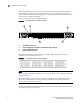
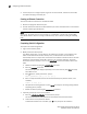
Figure 1 shows the port side of the Brocade 5000.
FIGURE 1 Port Side View of the Brocade 5000
The Fibre Channel ports are numbered from left to right, in eight-port groups, and are also
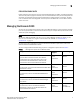
numbered on the faceplate (see Figure 2).
FIGURE 2 Port Numbering in the Brocade 5000
NOTE
Blade port numbers (physical port numbers) do not correspond directly to user port numbers (which are
displayed in Figure 2).
Brocade ISL Trunking is an optionally licensed software that allows you to create trunking groups of
ISLs between adjacent switches. For more information about Brocade ISL Trunking, refer to the
Brocade Fabric OS Administrator’s Guide.
The port side of the Brocade 5000 also displays the system status LED, power status LED, and port
status LEDs (see Figure 3 on page 16).
1 System Console Port
2 System Ethernet Port
3 Power Supply/Fan Assembly Field Replaceable Unit (2x)
4 Power Cord Retainer (2x)
5 Switch ID Pull Out Tab
4
5