
Technical data


Brocade 5000 Hardware Reference Manual 19
Publication Number: 53-1000424-03
Interpreting POST Results
3
Interpreting POST Results
POST is a system check that is performed each time the switch is powered on, rebooted, or reset,
and during which the LEDs flash different colors.
To determine whether POST completed successfully and whether any errors were detected:
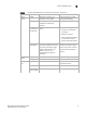
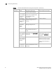
- Verify that the LEDs on the switch indicate that all components are healthy (LED patterns
are described in Table 2 on page 3-16). If one or more LEDs do not display a healthy state:
1. Verify that the LEDs are not set to “beacon” (this can be determined through the
switchShow command or Advanced Web Tools). For information about how to turn
beaconing on and off, refer to the Brocade Fabric OS Administrator’s Guide or the
Brocade Web Tools Administrator’s Guide.
2. Follow the recommended action for the observed LED behavior, as listed in
Table 2 on page 3-16.
- Verify that the switch prompt displays on the terminal of a computer workstation that is
connected to the switch.
If the prompt does not display when POST completes, press Enter. If the prompt still does
not display, open another telnet session or access the switch through another
management tool. If this is not successful, the switch did not successfully complete POST;
contact your switch supplier for repair.
- Review the system log for errors.
Any errors detected during POST are written to the system log, which is accessible through
the errShow command. For information about this command, refer to the Brocade Fabric
OS Command Reference. For information about error messages, refer to the Brocade
System Message Reference.
Maintaining the Brocade 5000
The Brocade 5000 does not require any regular physical maintenance and is designed for high
availability and to minimize the chance of failure. It includes diagnostic tests and field-replaceable
units, described in the following sections.
Diagnostic Tests
In addition to POST, Fabric OS includes diagnostic tests to help you troubleshoot the hardware and
firmware. This includes tests of internal connections and circuitry, fixed media, and the
transceivers and cables in use. The tests are implemented by command, either through a telnet
session or through a terminal set up for a serial connection to the switch. Some tests require the
ports to be connected by external cables, to allow diagnostics to verify the serializer/deserializer
interface, transceiver, and cable. Some tests require loop back plugs.
Diagnostic tests are run at link speeds of 1 Gbit/sec, 2 Gbit/sec, and 4 Gbit/sec.
NOTE
Diagnostic tests might temporarily lock the transmit and receive speed of the links during diagnostic
testing.