
Installation guide


Table Of Contents
- Contents
- Preface
- About This Document
- Brocade 5100 Introduction
- Brocade 5100 Installation and Configuration
- Brocade 5100 Operation
- Removal and Replacement of Combined Power Supply and Fan Assembly (Port-side Air Exhaust)
- Brocade 5100 Technical Specifications
- Regulatory Statements
- Cautions and Danger Notices
- Index
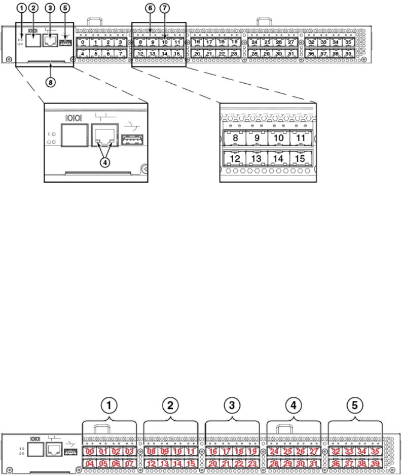
Port side of the Brocade 5100
The port side of the Brocade 5100 includes the system status LED, console port, Ethernet port and
LEDs, USB port, and Fibre Channel ports and the corresponding port status LEDs.
FIGURE 1 Port-side view of the Brocade 5100
1. System status (top) and power (bottom) LEDs
2. System RS232 console port (RJ-45)
3. System Ethernet port (RJ-45)
4. Ethernet port LEDs (green/amber)
5. USB port
6. Fibre Channel port status LED
7. Fibre Channel ports
8. Switch ID pull-out tab
Port Numbering
The Fibre Channel ports on the Brocade 5100 are numbered from left to right, in eight-port groups from
0 to 39 as illustrated in the following figure.
FIGURE 2 Trunking port groups and port numbers of the Brocade 5100
1. Trunking port group 1; FC ports 00-07
2. Trunking port group 1; FC ports 08-15
3. Trunking port group 1; FC ports 16-23
Port side of the Brocade 5100
Brocade 5100 Hardware Installation Guide 13
53-1000854-07