
Installation guide


Table Of Contents
- Contents
- Preface
- About This Document
- Brocade 5100 Introduction
- Brocade 5100 Installation and Configuration
- Brocade 5100 Operation
- Removal and Replacement of Combined Power Supply and Fan Assembly (Port-side Air Exhaust)
- Brocade 5100 Technical Specifications
- Regulatory Statements
- Cautions and Danger Notices
- Index
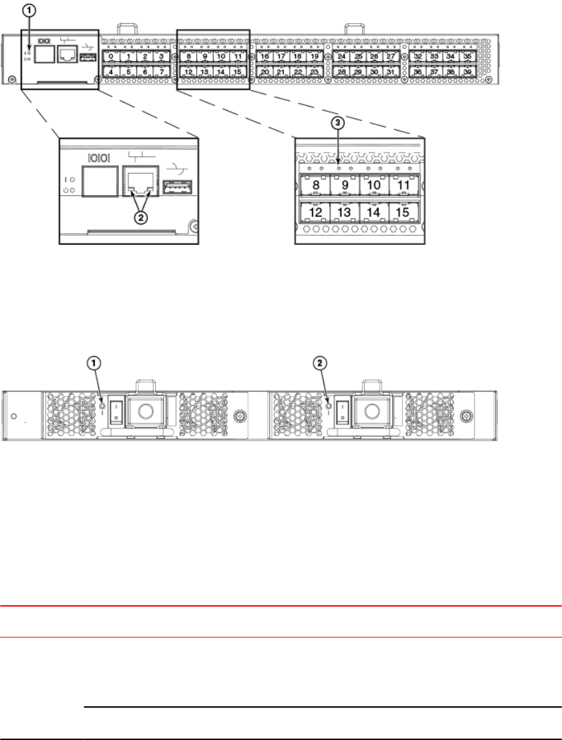
LED locations
FIGURE 4 Port Side LEDs on the Brocade 5100.
1. System status LED (top) and System power (bottom)
2. Ethernet port Status LEDs (green/amber)
3. FC port status (port 9)
FIGURE 5 Non-Port Side LEDs on the Brocade 5100.
1. Power supply status LED
2. Power supply status LED
LED Patterns
The following table describes the LEDs and their actions on the switch.
Brocade 5100 LED Patterns During Normal Operation TABLE 2
LED Name LED Color Status of Hardware Recommended Action
Power Supply
Status
No light Primary power cord is disconnected
or is not actively powered, or power
supply has failed.
Verify the power supply is on and
seated and the power cord is
connected to a functioning power
source.
Steady green Power supply is operating normally. No action required.
LED locations
28 Brocade 5100 Hardware Installation Guide
53-1000854-07