
Technical data
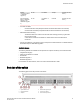
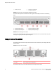
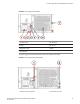

FIGURE 4 Power supply and fan details
1 AC power socket 5 AC status LED
2 Handle 6 Fan air inlet
3 Integral fan air inlet 7 Handle
4 DC status LED
The following figure shows the airflow labels on the power supply and fan FRUs.
FIGURE 5 Power supply and fan airflow labels
1 Airflow label for PSU integral fan
2 Airflow label for fan FRU
Introducing the Brocade 7840 Extension Switch
Brocade 7840 Extension Switch Hardware Reference Manual 15
53-1003127-02