53-1002483-03 21 November 2012 Brocade BigIron RX Series Hardware Installation Guide Supporting Multi-Service IronWare v02.9.
Copyright © 2011-2012 Brocade Communications Systems, Inc. All Rights Reserved. Brocade, Brocade Assurance, the B-wing symbol, BigIron, DCX, Fabric OS, FastIron, MLX, NetIron, SAN Health, ServerIron, TurboIron, VCS, and VDX are registered trademarks, and AnyIO, Brocade One, CloudPlex, Effortless Networking, ICX, NET Health, OpenScript, and The Effortless Network are trademarks of Brocade Communications Systems, Inc., in the United States and/or in other countries.
Contents About This Document Supported hardware and software . . . . . . . . . . . . . . . . . . . . . . . . . . . ix Document conventions . . . . . . . . . . . . . . . . . . . . . . . . . . . . . . . . . . . . . ix Text formatting . . . . . . . . . . . . . . . . . . . . . . . . . . . . . . . . . . . . . . . . ix Notes, cautions, and danger notices . . . . . . . . . . . . . . . . . . . . . . x Trademark references. . . . . . . . . . . . . . . . . . . . . . . . . . . . . . . . . . . . . .
Installing a BigIron RX-4 switch . . . . . . . . . . . . . . . . . . . . . . . . . . . . . 24 Preparing the installation site . . . . . . . . . . . . . . . . . . . . . . . . . . . 24 Unpacking a BigIron RX-4 switch . . . . . . . . . . . . . . . . . . . . . . . . 25 Chassis lifting guidelines for BigIron RX-4 switches . . . . . . . . . 25 Installing a BigIron RX-4 chassis in a rack . . . . . . . . . . . . . . . . . 25 Installing BigIron RX-4 modules . . . . . . . . . . . . . . . . . . . . . . . . .
Understanding how the management port functions. . . . . . . . . . . . 71 Connecting a BigIron RX Series switch . . . . . . . . . . . . . . . . . . . . . . . 71 4-port 10 Gigabit Ethernet module. . . . . . . . . . . . . . . . . . . . . . . 72 16-port 10 Gigabit Ethernet module . . . . . . . . . . . . . . . . . . . . . 72 Installing a fiber optic module . . . . . . . . . . . . . . . . . . . . . . . . . . 72 Cabling a fiber optic module . . . . . . . . . . . . . . . . . . . . . . . . . . . .
Replacing a switch fabric module . . . . . . . . . . . . . . . . . . . . . . . . . .109 Removing a switch fabric module. . . . . . . . . . . . . . . . . . . . . . .109 Installing a new switch fabric module . . . . . . . . . . . . . . . . . . .110 Replacing a fiber-optic transceiver . . . . . . . . . . . . . . . . . . . . . . . . .110 Removing a fiber-optic transceiver . . . . . . . . . . . . . . . . . . . . . .111 Installing a new fiber-optic transceiver. . . . . . . . . . . . . . . . . . .
Loading and saving configuration files . . . . . . . . . . . . . . . . . . . . . .145 Replacing the startup configuration with the running configuration . . . . . . . . . . . . . . . . . . . . . . . . . . . . . . . . . . . . . . .146 Replacing the running configuration with the startup configuration . . . . . . . . . . . . . . . . . . . . . . . . . . . . . . . . . . . . . . .146 Logging changes to the startup-config file . . . . . . . . . . . . . . . .
Korea . . . . . . . . . . . . . . . . . . . . . . . . . . . . . . . . . . . . . . . . . . . . . . . . .164 Class A statement . . . . . . . . . . . . . . . . . . . . . . . . . . . . . . . . . . .164 Russia . . . . . . . . . . . . . . . . . . . . . . . . . . . . . . . . . . . . . . . . . . . . . . . .164 Taiwan . . . . . . . . . . . . . . . . . . . . . . . . . . . . . . . . . . . . . . . . . . . . . . . .165 BSMI Statement . . . . . . . . . . . . . . . . . . . . . . . . . . . . . . . . . . . . .
About This Document In this chapter • Supported hardware and software. . . . . . . . . . . . . . . . . . . . . . . . . . . . . . . . . . • Document conventions . . . . . . . . . . . . . . . . . . . . . . . . . . . . . . . . . . . . . . . . . . . • Trademark references . . . . . . . . . . . . . . . . . . . . . . . . . . . . . . . . . . . . . . . . . . . . • Related publications . . . . . . . . . . . . . . . . . . . . . . . . . . . . . . . . . . . . . . . . . . . . . • Getting technical help . . . . . . . .
bold text Identifies command names Identifies the names of user-manipulated GUI elements Identifies keywords Identifies text to enter at the GUI or CLI italic text Provides emphasis Identifies variables Identifies document titles code text Identifies CLI output Notes, cautions, and danger notices The following notices and statements are used in this manual. They are listed below in order of increasing severity of potential hazards.
Related publications The following Brocade documents supplement the information in this guide and can be located at http://www.brocade.com/ethernetproducts: • BigIron RX Series Configuration Guide • Ironware MIB Reference Getting technical help To contact Technical Support, go to http://www.brocade.com/services-support/index.page for the latest e-mail and telephone contact information.
xii Brocade BigIron RX Series Hardware Installation Guide 53-1002483-03
Chapter Product Overview 1 In this chapter • Product overview . . . . . . . . . . . . . . . . . . . . . . . . . . . . . . . . . . . . . . . . . . . . . . . . 1 • Hardware features. . . . . . . . . . . . . . . . . . . . . . . . . . . . . . . . . . . . . . . . . . . . . . . 2 • Supported software features . . . . . . . . . . . . . . . . . . . . . . . . . . . . . . . . . . . . .
1 Hardware features Hardware features The BigIron RX Series switches are composed of the following major hardware components: • • • • • • • Chassis Management modules Interface modules Switch fabric module Power supplies Cooling system, which is composed of temperature sensors, fans, and fan control modules Rack mount kit The following sections provide more information about these components.
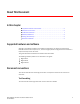
Hardware features FIGURE 2 1 BigIron RX-8 chassis 1 2 4 3 5 7 6 9 8 11 10 13 12 14 15 16 1 Interface slot 1 10 Interface slot 7 2 Interface slot 2 11 Interface slot 8 3 Interface slot 3 12 Management slot 1 4 Interface slot 4 13 Management slot 2 5 Switch fabric slot 1 14 Power supply slot 1 6 Switch fabric slot 2 15 Power supply slot 2 7 Switch fabric slot 3 16 Power supply slot 3 8 Interface slot 5 17 Power supply slot 4 9 Interface slot 6 18 ESD connec
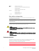
1 Hardware features FIGURE 3 BigIron RX-16 chassis 3 1 5 7 17 19 9 11 13 12 14 23 15 21 22 2 4 6 8 18 4 20 10 16 1 Interface slot 1 10 Interface slot 10 19 Switch fabric slot 3 2 Interface slot 2 11 Interface slot 11 20 Switch fabric slot 4 3 Interface slot 3 12 Interface slot 12 21 Management slot 1 4 Interface slot 4 13 Interface slot 13 22 Management slot 2 5 Interface slot 5 14 Interface slot 14 23 ESD connector 6 Interface slot 6 15 Interface slot
Hardware features 1 Interface slot 1 19 Interface slot 19 37 Switch fabric slot 5 2 Interface slot 2 20 Interface slot 20 38 Switch fabric slot 6 3 Interface slot 3 21 Interface slot 21 39 Switch fabric slot 7 4 Interface slot 4 22 Interface slot 22 40 Switch fabric slot 8 5 Interface slot 5 23 Interface slot 23 41 Management slot 1 6 Interface slot 6 24 Interface slot 24 42 Management slot 2 7 Interface slot 7 25 Interface slot 25 43 Captive screws 8 Interface sl
1 Hardware features BigIron RX-8 Upon shipment from the factory, the following components are installed in the BigIron RX-8 chassis as described: • Two switch fabric modules. • A slot blank in each interface module slot. The slot blank covers a slot that does not currently have a module installed in it, ensuring proper airflow within the chassis. • A fan tray assembly, which is located in the front right side of the chassis. For more information about the fans, refer to “Cooling system” on page 17.
Hardware features 1 Figure 1, Figure 2, and Figure 3show the BigIron RX Series chassis and the slots into which you install the various modules. You must install the primary power supplies and the redundant power supplies as described in the figures. Figure 1, Figure 2, and Figure 3 also show an electrostatic discharge (ESD) connector, into which you can plug an ESD wrist strap to ground yourself while handling and installing modules.
1 Hardware features PCMCIA slots The PCMCIA slots support a flash PC card. The flash PC card provides storage space in addition to the system’s flash memory. A flash PC card can store system files, including boot images, startup configuration files, running configuration files, and so on. As a result, you can perform system management tasks, such as copying files between flash PC cards, copying files between a flash PC card and flash memory, and so on.
Hardware features TABLE 1 1 Management module LEDs (Continued) LED Position State Meaning 10/100/100 0 Ethernet Port Above and right of RJ-45 connector On (Green) A link is established with the remote port. Off A link is not established with the remote port. 10/100/100 0 Ethernet Port Above and left of RJ-45 connector On or blinking (Yellow) The port is transmitting and receiving packets. Off for an extended period The port is not transmitting or receiving packets.
1 Hardware features TABLE 2 10 Gigabit Ethernet module LEDs LED Position State Meaning Link Left of each Ethernet port On A link is established with the remote port. Off A link is not established with the remote port. Left of each Ethernet port On or blinking The port is transmitting and receiving packets. Off for an extended period The port is not transmitting or receiving packets.
Hardware features 1 The following optic modules versions are available from Brocade: • Short wavelength (86 – 300 meters) – Brocade part number 10G-XFP-SR • Long wavelength (10 kilometers) – Brocade part number 10G-XFP-LR • Extra long wavelength (40 kilometers) – Brocade part number 10G-XFP-ER 16-port 10 Gigabit Ethernet oversubscribed module The 16 x 10GE oversubscribed module for the BigIron RX plugs into any port slot of the switch and is compatible with all previous generations of card on that switc
1 Hardware features High speed fans requirements • TheBigIron RX 16 requires upgrading of the rear fan modules to NI-X-16-FAN-EXH-A modules. If the BigIron RX switch is not upgraded to support NI-X-16-FAN-EXH-A modules when 16x10G modules are in the BigIron RX system, then the syslog message such as the following will be displayed: SYSLOG: Mar 26 14:19:53:<12>R1, 16x10G modules in slots 10,11,13,16 must not be running without high speed fans.
Hardware features 1 NOTE The device will be FE or GE capable, but will only display that is GE to indicate the maximum speed capability of the module. NOTE The actual speed will be displayed once the link is seen and the port auto-senses the speed of the SFP. You can issue the show media command to display the type of optic installed and determine the speed the port will run at when the link is received. Figure 7 shows the 24-port 1 Gigabit Ethernet mini-GBIC (or SFP) module’s front panel.
1 Hardware features • LEDs • 24 1-Gigabit Ethernet ports TABLE 6 Gigabit Ethernet module LEDs LED Position State Meaning Link Left of each Ethernet port On A link is established with the remote port. Off A link is not established with the remote port. Left of each Ethernet port On or blinking The port is transmitting and receiving packets. Off for an extended period The port is not transmitting or receiving packets.
Hardware features 1 High speed fans requirements • TheBigIron RX 16 requires upgrading of the rear fan modules to NI-X-16-FAN-EXH-A modules. If the BigIron RX switch is not upgraded to support NI-X-16-FAN-EXH-A modules when 48x1G modules are in the BigIron RX system, then the syslog message such as the following will be displayed: SYSLOG: Mar 26 14:19:53:<12>R1, 48x1G modules in slots 10,11,13,16 must not be running without high speed fans.
1 Hardware features Figure 10 shows the switch fabric module’s front panel. FIGURE 10 Switch fabric module front panel Pwr BI-SWF Active The front panel includes two LEDs, which Table 7 describes. TABLE 7 Switch fabric module LEDs LED Position State Meaning Pwr Above Active LED On The module is receiving power. Off The module is not receiving power. On The chassis switch fabric is active and ready to switch user packets.
Hardware features 1 Each power supply has three LEDs on its faceplate that provide status for the input power, output power and notification of alarms sent. If the input power and output power LEDs are on (a steady green), the power supply is providing power to the chassis components. The power supplies are hot swappable, which means you can remove and replace them without powering down the system.
1 Hardware features FIGURE 12 Fan component locations for the BigIron RX-8 1 1 Fan module FIGURE 13 Front fan component locations for the BigIron RX-16 1 1 18 Front fan assembly Brocade BigIron RX Series Hardware Installation Guide 53-1002483-03
Hardware features FIGURE 14 1 Rear fan component locations for the BigIron RX-16 1 1 Fan modules Upon system startup, the fans in the BigIron RX Series switches operate at high speed, then the management module lowers the fan speed to low speed. By default, the BigIron RX Series switch polls the temperature sensor on each module every 60 seconds to get a temperature reading.
1 Supported software features TABLE 8 Fan control module LED LED Position State Meaning Fan control module LED Rear of chassis Off The fans are not receiving power. Green The fans are working and responding to controls from the fan control module. Amber The fans are not working and not responding to controls from the fan control module. CAUTION To avoid overheating of the BigIron RX Series chassis, do not remove more than one fan at a time.
Chapter 2 Installing the BigIron RX Series Switch In this chapter • Installation precautions . . . . . . . . . . . . . . . . . . . . . . . . . . . . . . . . . . . . . . . . . • Installing a BigIron RX-4 switch . . . . . . . . . . . . . . . . . . . . . . . . . . . . . . . . . . . • Installing a BigIron RX-16 switch . . . . . . . . . . . . . . . . . . . . . . . . . . . . . . . . . . • Attaching a management station . . . . . . . . . . . . . . . . . . . . . . . . . . . . . . . . . .
2 Installation precautions CAUTION Do not install the device in an environment where the operating ambient temperature might exceed 40o C (104o F). CAUTION Make sure the air flow around the front, sides, and back of the device is not restricted. CAUTION If you do not install a module in a slot, you must keep the slot blank in place. If you run the chassis with an uncovered slot, the system may overheat. CAUTION Never leave tools inside the chassis.
Installation precautions 2 DANGER If the installation requires a different power cord than the one supplied with the device, make sure you use a power cord displaying the mark of the safety agency that defines the regulations for power cords in your country. The mark is your assurance that the power cord can be used safely with the device. DANGER Make sure the rack or cabinet housing the device is adequately secured to prevent it from becoming unstable or falling over.
2 Installing a BigIron RX-4 switch TABLE 9 The American Wire Gauge (AWG) guidelines AWG Ohms per 100 feet Maximum Amps for chassis wiring Maximum Amps for power transmission 5 0.3133 118 47 6 0.3951 101 37 7 0.4982 89 30 8 0.6282 73 24 9 0.7921 64 19 10 0.9989 55 15 11 1.26 47 12 12 1.588 41 9.3 CAUTION For the DC input circuit to the system, make sure there is a UL-Listed 30 amp circuit breaker, minimum -48Vdc, double pole, on the input to the terminal block.
Installing a BigIron RX-4 switch 2 Installation location Before installing the switch, plan its location and orientation relative to other devices and equipment. For cooling purposes, allow a minimum of six inches of space between the sides, front, and the back of the chassis and walls or other obstructions. If a chassis is installed within a perforated enclosure, the perforations must have openings on at least 60 percent of the surface.
2 Installing a BigIron RX-4 switch Preparing to mount a BigIron RX-4 chassis in a rack Because of the weight of a fully loaded BigIron RX-4 chassis, Brocade recommends mounting a chassis in a rack before installing the modules and AC power supplies if necessary. In a standard 19-inch (EIA310-D) rack, you can install up to ten BigIron RX-4 chassis. For each BigIron RX-4 chassis that you install in a rack, you must provide four standard #12-24 pan-head screws with which to mount and secure the chassis.
Installing a BigIron RX-4 switch FIGURE 16 Positioning the screws in a rack 5" 3" 1 1 2 Unequal flange equipment rack 2 2 Network equipment rack 3. Starting with the chassis that you want to mount in the lowest position in the rack, mount the chassis in the rack as shown in Figure 17. With two or more people lifting the chassis, slip the wide portion of each keyhole slot over the corresponding screw in the rack.
2 Installing a BigIron RX-4 switch NOTE To provide better grounding of the chassis to the rack, attach the chassis to the rack using star washers. Additionally, if any single hole grounding lugs are used star washers shall be used as a means to prevent rotation of the lug. 6. Add additional screws as required. 7. Repeat step 2 through step 6 to mount each subsequent chassis in the same rack. Removing the slot blanks The BigIron RX-4 chassis ships with slot blanks installed in all module slots.
Installing a BigIron RX-4 switch 2 The BigIron RX-4 chassis ships with the required switch fabric modules installed. TABLE 10 BigIron RX-4 module installation BigIron RX-4 module Chassis slot number Management modules Active module – M1 (left). Redundant module – M2 (right). Interface modules 1–4 Switch fabric modules SF1 – SF3 CAUTION If you do not install a module in a slot, you must leave the slot blank installed in the slot.
2 Installing a BigIron RX-4 switch FIGURE 18 Installing a module in a BigIron RX-4 chassis 1 1 Management module NOTE When inserting the module into the chassis, make sure that the faceplate does not overlap with the faceplate of an adjacent interface module. 4. Push the ejectors in until they are flush with the module front panel. This action will fully seat the module in the backplane. Modules have a snug fit for maximum EMI protection.
Installing a BigIron RX-4 switch 2 CAUTION Carefully follow the mechanical guides on each side of the power supply slot and make sure the power supply is properly inserted in the guides. Never insert the power supply upside down. FIGURE 19 Installing a power supply in a BigIron RX-4 chassis 1 1 Power supply 4. After the power supply is fully inserted, push the power supply front panel toward the back of the chassis. This action causes the power supply connector to seat into the backplane connector.
2 Installing a BigIron RX-4 switch FIGURE 20 Connecting a power cord to the power supply in a BigIron RX-4 chassis 3 2 1 1 Ground point 2 Power cord 3 Cord retainer DANGER If the installation requires a different power cord than the one supplied with the device, make sure you use a power cord displaying the mark of the safety agency that defines the regulations for power cords in your country. The mark is your assurance that the power cord can be used safely with the device. 4.
Installing a BigIron RX-4 switch 2 1. Use a flat-blade screwdriver to remove the two screws holding the transparent cover over the power supply lugs. FIGURE 21 The BigIron RX-4 DC power supply 1 DC DC ALM IN OK 2 1 Screws holding power lugs 2 Screws holding transparent cover 2. Use a Phillips head screwdriver to remove each of the power lugs. 3. Crimp #8 AWG power supply wire into the power lugs and reconnect the power lugs to the power supply unit.
2 Installing a BigIron RX-8 switch Installing a BigIron RX-8 switch This section describes the following tasks: • • • • • • • • • “Preparing the installation site” “Unpacking a BigIron RX-8 switch” “Chassis lifting guidelines for BigIron RX-8 switches” “Installing the BigIron RX-8 chassis in a rack” “Installing BigIron RX-8 modules” “Installing power supplies in the BigIron RX-8 chassis” “Connecting AC power to a BigIron RX-8 chassis” “Connecting DC power to a BigIron RX-8 chassis” “Final steps” Prepar
Installing a BigIron RX-8 switch 2 3. Remove the strap that secures the shipping carton to the pallet. 4. Remove the plastic cover and shipping carton. 5. Save the shipping carton, pallet, and packing materials in case you need to move or ship the chassis at a later time. Chassis lifting guidelines for BigIron RX-8 switches DANGER A fully-populated BigIron RX-8, chassis is heavy. TWO OR MORE PEOPLE ARE REQUIRED WHEN LIFTING, HANDLING, OR MOUNTING THESE DEVICES.
2 Installing a BigIron RX-8 switch FIGURE 23 Removing the extra screws used for shipment 1 2 3 1 Chassis front 2 Chassis rear 3 Shipping screws Mounting a BigIron RX-8 chassis in a rack Follow the steps given below to mount a BigIron RX-8, chassis in a rack. 1. Determine the position of each chassis in the rack, for example, a chassis with the fewest modules on top, a chassis with more modules than the top chassis in the middle, and a fully populated chassis on the bottom. 2.
Installing a BigIron RX-8 switch 2 3. Starting with the chassis that you want to mount in the lowest position in the rack, mount the chassis in the rack as shown in Figure 25. With two or more people lifting the chassis, slip the wide portion of each keyhole slot over the corresponding screw in the rack. FIGURE 25 Mounting the BigIron RX-8 chassis in a rack 1 1 Standard 19-inch rack 4. Slide the chassis down so that the screw heads are in the narrow portion of the keyhole slots. 5.
2 Installing a BigIron RX-8 switch Although the slot blanks are different in size, the procedure for removing them from the BigIron RX-8 chassis is the same. Therefore, this section provides one procedure that applies to all slot blanks. You will need a flat-head screwdriver to perform this task. Follow the steps given below to remove a slot blank. 1. Loosen the screws on either end of the slot blank by hand or with a flat-head screwdriver. 2.
Installing a BigIron RX-8 switch 2 Before installing a module in the BigIron RX-8 chassis, have the following on hand: • An ESD wrist strap with a plug for connection to the ESD connector on the BigIron RX-8 chassis. DANGER For safety reasons, the ESD wrist strap should contain a 1 meg ohm series resistor. • A large flat-head screwdriver. Follow the steps given below to install a module in the BigIron RX-8 chassis. 1.
2 Installing a BigIron RX-8 switch Installing power supplies in the BigIron RX-8 chassis The BigIron RX-8 accommodates three power supplies (AC or DC) with one required and two redundant. It is shipped with one power supply. You must purchase one or two additional power supplies if you want your BigIron RX-8 equipped for redundancy. Follow the steps given below to install a power supply in the BigIron RX-8 chassis. 1. Remove the blank power supply faceplate, and expose the empty power supply slot. 2.
Installing a BigIron RX-8 switch 2 Connecting AC power to a BigIron RX-8 chassis AC power is supplied through an AC power cord that is installed at the rear of the BigIron RX-8 chassis. 1. At the rear of the BigIron RX-8 chassis, locate the power receptacle where the power supplies have been installed. 2. Lift the cord-retainer and connect a Brocade-supplied AC power cord to the power supply. 3. Snap the cord-retainer over the power plug to hold it in place.
2 Installing a BigIron RX-8 switch Connecting DC power to a BigIron RX-8 chassis You can use a DC power source for the BigIron RX-8 chassis. This is supported through use of a DC-to-DC power supply. DC power must be supplied at 48 V and 30 A. The DC-to-DC supply provides the DC power to the chassis at 12 V and 100 A. DANGER The procedure in this section is for qualified service personnel. Follow the steps given below to connect a DC power source. 1.
Installing a BigIron RX-16 switch 2 Final steps Follow the steps listed below to complete the installation: • “Attaching a management station” • “Powering-on the power source” • “Verifying proper operation” Installing a BigIron RX-16 switch This section describes the following tasks: • • • • • • • • • “Preparing the installation site” “Unpacking a BigIron RX-16 switch” “Chassis lifting guidelines for BigIron RX-16 switches” “Installing a BigIron RX-16 chassis in a rack” “Installing BigIron RX-16 modul
2 Installing a BigIron RX-16 switch • BigIron RX-16 chassis with the appropriate number of switch fabric modules already installed in the slot marked SF and slot blanks installed in all other module slots. • Rack mount kit, including two L-shaped brackets and mounting screws. NOTE You must provide standard #12-24 pan-head screws for mounting the BigIron RX Series chassis into a rack. • A 115V AC power cable for each AC power supply you purchase from Brocade.
Installing a BigIron RX-16 switch 2 Installing a BigIron RX-16 chassis in a rack Preparing to mount a BigIron RX-16 chassis in a rack Keep the following in mind when mounting a BigIron RX-16 chassis in a rack: DANGER A fully-populated BigIron RX-16 chassis is heavy. TWO OR MORE PEOPLE ARE REQUIRED WHEN LIFTING, HANDLING, OR MOUNTING THESE DEVICES. Do not use the handles on the power supply units to lift or carry chassis devices.
2 Installing a BigIron RX-16 switch Mounting a BigIron RX-16 chassis in a rack Follow the steps given below to mount a BigIron RX-16 chassis in a rack. 1. Determine the position of each chassis in the rack, for example, a chassis with the fewest modules on top, a chassis with more modules than the top chassis in the middle, and a fully populated chassis on the bottom. 2.
Installing a BigIron RX-16 switch FIGURE 32 2 Mounting the BigIron RX-16 chassis in a rack 4. Slide the chassis down so that the screw heads are in the narrow portion of the keyhole slots. 5. Tighten the screws to secure the chassis in place. NOTE To provide better grounding of the chassis to the rack, attach the chassis to the rack using star washers. Additionally, if any single hole grounding lugs are used star washers shall be used as a means to prevent rotation of the lug. 6.
2 Installing a BigIron RX-16 switch Follow the steps given below to remove a slot blank. 1. Loosen the screws on either end of the slot blank by hand or with a flat-head screwdriver. 2. Pull the slot blank out of the chassis, and store it in a safe place for future use. Installing BigIron RX-16 modules This section provides one procedure that applies to all modules. The sequence for installing more than one module is important to ensure proper fit.
Installing a BigIron RX-16 switch 2 Follow the steps given below to install a module in the BigIron RX-16 chassis. 1. Put on the ESD wrist strap and ground yourself by inserting the plug into the ESD connector on the chassis front. 2. Remove the module from its packaging. 3. With the ejectors in the outward position, insert the module into the appropriate chassis slot and slide the card along the card guide until the ejectors on either side of the module move close to the module front panel.
2 Installing a BigIron RX-16 switch Populating a BigIron RX-16 chassis The sequence for installing more than one card is important to ensure proper fit in the BigIron RX-16 chassis. Always fill the bottom slots in the BigIron RX-16 first. Begin by filling the slots from the left side of the chassis, and working your way towards the right. Refer to “BigIron RX-16 chassis” on page 4 for slot locations. NOTE Any empty slots must contain slot blanks to ensure proper air flow within the chassis.
Installing a BigIron RX-16 switch FIGURE 34 2 Installing a power supply in a BigIron RX-16 chassis 1 2 1 Power supply 2 Release latch CAUTION Carefully follow the mechanical guides on each side of the power supply slot and make sure the power supply is properly inserted in the guides. Never insert the power supply upside down. 4. After the power supply is fully inserted, push the power supply front panel toward the back of the chassis.
2 Installing a BigIron RX-16 switch 3. Snap the cord-retainer over the power plug to hold it in place.
Installing a BigIron RX-16 switch 2 Follow the steps given below to connect a DC power source. 1. Use a flat-blade screwdriver to remove the two screws holding the transparent cover over the power supply lugs. FIGURE 36 The BigIron RX-8 and BigIron RX-16 DC power supply 1 DC IN DC OUT ALM 2 1 Screws holding power lugs 2 Screws holding transparent cover 2. Use a Phillips head screwdriver to remove each of the power lugs. 3.
2 Attaching a management station Attaching a management station You can manage the BigIron RX Series system in the following ways: • You can connect a PC or terminal to the management module’s serial (Console) port for a direct connection. From this interface, you can configure the 10BaseT/100BaseTX/1000BaseTX Ethernet (management) port with an IP address and either Telnet or SSH.
Powering-on the power source • • • • • 2 Baud: 9600 bps Data bits: 8 Parity: None Stop bits: 1 Flow control: None Attaching the management module’s Ethernet Port to a network The management module’s 10BaseT/100BaseTX/1000BaseTX Ethernet (management) port (RJ-45 UTP connector) allows you to connect the management port to a network. A management station in your existing management network can then access a BigIron RX Series switch using the IronView Network Manager.
2 Verifying proper operation Insert the other end into a 115V or 120V wall outlet. Repeat this step for each installed AC power supply. DANGER If the installation requires a different power cord than the one supplied with the device, make sure you use a power cord displaying the mark of the safety agency that defines the regulations for power cords in your country. The mark is your assurance that the power cord can be used safely with the device.
Verifying proper operation TABLE 13 LED 2 Desired and abnormal LED states after system power on Desired state Meaning Abnormal state Meaning or action Management module Active The Active LED on one of the installed management modules should be on. The module is functioning as the active management module. Off Neither of the management modules is managing the switch fabric and interface modules. A problem could have occurred during initialization.
2 Verifying proper operation TABLE 13 Desired and abnormal LED states after system power on (Continued) LED Desired state Meaning Abnormal state Meaning or action Pwr On The module is receiving power. Off The module is not receiving power. You can do the following: • Make certain that the module is installed properly. For more information, refer to “Installing BigIron RX-4 modules” on page 28, “Installing BigIron RX-8 modules” on page 38, and “Installing BigIron RX-16 modules” on page 48.
Verifying proper operation TABLE 13 2 Desired and abnormal LED states after system power on (Continued) LED Desired state Meaning Abnormal state Meaning or action Link On A link is established with the remote port. Off At this stage of the installation, you have not yet cabled the interface module ports, so this LED will be off. After cabling this port, if this LED is off, a link is not established with the remote port. For more information, refer to Table 15 on page 75.
2 Verifying proper operation TABLE 13 Desired and abnormal LED states after system power on (Continued) LED Desired state Meaning Abnormal state Meaning or action DC OK Green (steady) The power supply is providing DC power to the BigIron RX Series chassis. Off The power supply is not supplying power to the chassis. If the AC OK LED is lit Green, then there is a problem with the power supply and it must be replaced. ALM ALM The power supply is in normal operating condition.
Verifying proper operation TABLE 13 2 Desired and abnormal LED states after system power on (Continued) LED Desired state Meaning Abnormal state Meaning or action Off or amber The fans are not receiving power (off), or the fans are not working and not responding to controls from the fan control module (amber). You can do the following: • If the LED is off, check the power LED on the other modules to make sure they are receiving power.
2 Verifying proper operation If you do not see this prompt, do the following. 1. Make sure the cable is securely connected to your PC or terminal and the Console port or Ethernet port. 2. Check the settings in your terminal emulation program. In addition to the session settings listed in “Attaching a PC or terminal to the Console port or Ethernet port” on page 54, make sure the terminal emulation session is running on the same serial port you attached to the Console port.
Verifying proper operation 2 • CARD_STATE_FAILED – The management module was unable to bring up an interface module properly. If you observe this status, make certain that the interface module is installed properly. For more information, refer to “Installing BigIron RX-4 modules” on page 28, “Installing BigIron RX-8 modules” on page 38, and “Installing BigIron RX-16 modules” on page 48. • CARD_DOWN_REASON_ – The module is in a nonfunctional state.
2 64 Verifying proper operation Brocade BigIron RX Series Hardware Installation Guide 53-1002483-03
Chapter Connecting a BigIron RX Series Switch to a Network Device 3 In this chapter • Assigning passwords . . . . . . . . . . . . . . . . . . . . . . . . . . . . . . . . . . . . . . . . . . . . • Configuring IP addresses . . . . . . . . . . . . . . . . . . . . . . . . . . . . . . . . . . . . . . . . • Understanding how the management port functions . . . . . . . . . . . . . . . . . . • Connecting a BigIron RX Series switch . . . . . . . . . . . . . . . . . . . . . . . . . . . . .
3 Assigning passwords NOTE When you upgrade to Release 02.2.01 or later, the old passwords are still valid; however, users must change their passwords to follow the new format to take advantage of this password enhancement. There are no new CLI commands for this feature. Login lockout The CLI provides up to three login attempts. If a user fails to login after three attempts, that user is locked out (disabled).
Assigning passwords 3 For example: SSH@BigIron RX(config)# username sandy expires 20 SSH@BigIron RX(config)# show user Username Password Encrypt Priv Status Expire Time =============================================================================== === sandy $1$Gz...uX/$wQ44fVGtsqbKWkQknzAZ6. enabled 0 enabled 20 days The CLI contains the following access levels: • User EXEC – The level you enter when you first start a CLI session.
3 Configuring IP addresses NOTE You must set the super-user password before you can set other types of passwords. 4. Enter the following commands to set the port configuration and read-only passwords: BigIron RX(config)# enable port-config-password BigIron RX(config)# enable read-only-password Syntax: enable super-user-password | read-only-password | port-config-password Passwords can be up to 48 characters long.
Configuring IP addresses 3 Assigning an IP address to a management interface Instead of assigning a global IP address to the BigIron RX Series switch for system management purposes, you now assign an IP address to the management interface. The IP address is assigned to the active management module port. If the active management module becomes unavailable and the redundant module becomes the active module, the IP address is assigned to the new active management module port.
3 Configuring IP addresses You must use the serial connection to assign the first IP address. For subsequent addresses, you also can use the CLI through Telnet or the Web management interface. You can use IronView Network Manager to assign IP addresses to virtual routing interfaces only. By default, you can configure up to 24 IP interfaces on each interface, virtual interface, and loopback interface. For example, to assign the IP address 192.22.3.44 and sub-net mask 255.255.255.
Understanding how the management port functions 3 Syntax: enable You can disable each of these interfaces using the disable command at the appropriate interface configuration level of the CLI.
3 Connecting a BigIron RX Series switch The sections “Installing a fiber optic module” on page 72 and “Cabling a fiber optic module” on page 73 provide information about performing these tasks. Also refer to “Enhanced Digital Optical Monitoring” on page 73 for information on cleaning the fiber optic connectors and troubleshooting network connections.
Connecting a BigIron RX Series switch 3 To install a fiber optic module into an Ethernet port, do the following. 1. Put on the ESD wrist strap and ground yourself by inserting the plug into the ESD connector located in the upper right corner of the chassis front. 2. Remove the module from its protective packaging. 3. Remove the metal cover from the port on the interface module’s control panel. 4. Gently insert the fiber optic module into the port until the module clicks into place.
3 Connecting a BigIron RX Series switch You can view the optical monitoring information using the show optic command as displayed in the following: BigIron RX#show optic 4 Port Temperature Tx Power Rx Power Tx Bias Current Monitor +----+-----------+--------------+--------------+---------------+-------+ 4/1 30.8242 C -001.8822 dBm -002.5908 dBm 41.790 mA Normal Normal Normal Normal 4/2 31.7070 C -001.4116 dBm -006.4092 dBm 41.976 mA Normal Normal Normal Normal 4/3 30.1835 C -000.5794 dBm 0.
Connecting a BigIron RX Series switch 3 Troubleshooting network connections After you cable the fiber optic modules, you can observe certain LEDs to determine if the network connections are functioning properly. Table 15 outlines the LEDs related to the network connections, the desired state of each LED, possible abnormal states of each LED, and what to do if an LED indicates an abnormal state.
3 Testing network connectivity Testing network connectivity After you cable the fiber optic modules, you can test connectivity to other network devices by pinging those devices. You also can perform trace routes. To resolve problems that may arise with network connections: • For the indicated port, verify that both ends of the cabling (at the Brocade device and the connected device) are snug. • Verify that the Brocade device and the connected device are both powered on and operating correctly.
Testing network connectivity 3 The CLI displays trace route information for each hop as soon as the information is received. Traceroute requests display all responses to a given TTL. In addition, if there are multiple equal-cost routes to the destination, the Brocade device displays up to three responses by default. Refer to the BigIron RX Series Configuration Guide for information about the command syntax.
3 Testing network connectivity Table 16 defines the fields shown in the command output. TABLE 16 This line... Displays... Port The interface that was tested. Speed The port’s current line speed. Local pair The local link name. Pair Length The cable length when terminated, or the distance to the point of fault when the line is not up. Remote pair The remote link name. Pair status 78 Cable statistics The status of the link.
Chapter 4 Managing the BigIron RX Series Chassis and Modules In this chapter • Managing the BigIron RX Series chassis . . . . . . . . . . . . . . . . . . . . . . . . . . . . • Managing the cooling system . . . . . . . . . . . . . . . . . . . . . . . . . . . . . . . . . . . . . • Managing the interface modules . . . . . . . . . . . . . . . . . . . . . . . . . . . . . . . . . . • Enabling and disabling management module CPU usage calculations . . . • Displaying management module CPU usage. . . . . . . . .
4 Managing the BigIron RX Series chassis ---POWERS --AC Powers Are Used. Power 1: Installed (OK) Power 2: not present Power 3: not present Slot Power-On Priority: Slot1 (pri=1) Slot2 (pri=1) Slot3 (pri=1) Slot4 (pri=1) --- FANS --Right Fan Tray: Fan 5: Status = OK, Speed = LOW (50%) (RPM 3333) Right Fan Tray: Fan 6: Status = OK, Speed = LOW (50%) (RPM 3409) --- TEMPERATURE READINGS --Active Mgmt Module: 32.500C 54.625C (CPU) SNM1: 27.5C SNM2: 30.5C SNM3: 30.5C LP2 Sensor1: 41.
Managing the BigIron RX Series chassis TABLE 17 4 Chassis status and temperature information (Continued) This field... Displays... Speed The speed of a fan can be one of the following: Low – The fan is functioning at 50 percent of capacity. Medium – The fan is functioning at 75 percent of capacity. Medium-high – The fan is functioning at 90 percent of capacity. High – The fan is functioning at 100 percent of capacity.
4 Managing the BigIron RX Series chassis TABLE 18 Syslog buffer configuration (Continued) This field... Displays... overruns The number of times the dynamic log buffer has filled up and been cleared to hold new entries. For example, if the buffer is set for 100 entries, the 101st entry causes an overrun. After that, the 201st entry causes a second overrun. level The message levels that are enabled. Each letter represents a message type and is identified by the key (level code) below the value.
Managing the cooling system 4 You can specify the dynamic-buffer keyword to clear the dynamic buffer or the static-buffer keyword to clear the static buffer. If you do not specify a buffer, both buffers are cleared. Managing the cooling system This section provides configuration, management, and monitoring information about the BigIron RX Series cooling system. Configuring the cooling system The BigIron RX Series switch provides default settings for all cooling system parameters.
4 Managing the cooling system • If the temperature of a management module, the switch fabric module, and all interface modules falls below the low threshold for a fan speed, the fan decreases its speed to the next lower speed. If the temperature of all modules falls below the high threshold for the low speed, the fan operates at the low speed.
Managing the cooling system 4 Syntax: fan-threshold [low ] [med ] [med-hi ] [hi ] For the parameter, you can specify the following: • lp – Changes low and high temperature thresholds for the interface modules. • mp – Changes low and high temperature thresholds for the active and standby management modules.
4 Managing the cooling system Fan Speed Med-Hi: 51 - 60 Fan Speed Hi: 56 - 85 state = 0 (FAN_STATE_LOW) max_ts_shut_off_count = 3 shut_off_count = 0 0 0 0 0 === Thermal Sensor Control Fan Speed Low: -1 - 60 Fan Speed Med: 57 - 70 Fan Speed Med-Hi: 67 - 80 Fan Speed Hi: 77 - 85 state = 0 (FAN_STATE_LOW) max_ts_shut_off_count = 3 shut_off_count = 0 0 0 0 0 === Thermal Sensor Control Fan Speed Low: -1 - 60 Fan Speed Med: 57 - 70 Fan Speed Med-Hi: 67 - 80 Fan Speed Hi: 77 - 85 state = 0 (FAN_STATE_LOW) max_ts
Managing the cooling system 4 Changing the temperature polling interval By default, the BigIron RX Series system reads the temperature sensor on each module every 60 seconds. To change the interval at which the system reads the temperature sensors on each module, enter a command such as the following at the global CONFIG level of the CLI: BigIron RX(config)# temp-poll-period 120 Syntax: temp-poll-period For the parameter, you can specify a value from 30 – 120.
4 Managing the interface modules BigIron RX# show chassis ... --- FANS --Right Fan Tray: Fan 5: Status = OK, Speed = LOW (50%) (RPM 3333) Right Fan Tray: Fan 6: Status = OK, Speed = LOW (50%) (RPM 3488)... Syntax: show chassis For information about all output generated by the show chassis command,refer to “Displaying chassis status and temperature readings” on page 79. TABLE 21 This field... Status Speed Fan status and speed fields Displays...
Managing the interface modules 4 Configuring interface module boot parameters The Ethernet interface module has its own system software and boots after the management module boots. By default, the following boot-related events occur: • The BigIron RX Series system synchronizes or prompts you to synchronize the interface modules’ IronWare images between the management module and the interface modules.
4 Managing the interface modules Synchronizing the interface modules’ IronWare images during bootup By default, the BigIron RX Series system checks the IronWare images in the interface module’s flash memory during boot to ensure they are the same as the IronWare images in the management module’s flash memory. If an interface module does not have an IronWare image, the system automatically downloads the image from the management module’s flash memory to the interface module’s flash memory.
Managing the interface modules 4 Syntax: no lp disable-lp-sync-check Changing the boot source By default, the interface modules boot from the primary IronWare image located in the interface modules’ flash memory.
4 Managing the interface modules The parameter specifies the BigIron RX chassis slot number that contains the interface module that will undergo an immediate boot. You can specify 1 – 4 for BigIron RX-4, 1 – 8 for BigIron RX-8 or 1 – 16 for BigIron RX-16.
Managing the interface modules 4 Specifying an immediate interactive boot To specify an immediate interactive boot for the interface module installed in slot 1, enter the following command at the Privileged EXEC level of the CLI: BigIron RX# lp boot system interactive 1 Syntax: lp boot system interactive The parameter specifies the BigIron RX Series chassis slot number that contains the interface module that will undergo an immediate boot.
4 Managing the interface modules The all | parameter specifies that the automatic boot applies to all interface modules in the BigIron RX Series chassis or to an interface module in the specified chassis slot number only. You can specify 1 – 4 for BigIron RX-4, 1 – 8 for BigIron RX-8 or 1 – 16 for BigIron RX-16.
Managing the interface modules 4 After you enter this command, the system enters the interface module’s monitor mode. For example, to boot from the primary IronWare image in the interface module’s flash memory, enter the following command at the monitor prompt: LP MONITOR> boot system flash primary Changing priority of chassis slots for interface modules You can prioritize the BigIron RX Series chassis slots in which the interface modules are installed.
4 Enabling and disabling management module CPU usage calculations Disabling and reenabling power to the switch fabric modules If needed, you can disable power to a specified switch fabric module and then reenable it. For example, to disable power to the SFM, enter the following command at the Privileged EXEC level of the CLI: BigIron RX# power-off snm 1 Syntax: power-off snm The parameter indicates the switch fabric module number for which you are disabling the power.
Displaying management module CPU usage 4 NOTE When finished gathering statistics for debugging purposes, Brocade recommends disabling the usage averaging calculations, which are CPU-intensive and can affect the performance of the management module. Displaying management module CPU usage You can display the tasks handled by the management module and the amount of the management module’s CPU used by each task.
4 Removing MAC address entries A problem could exist if the CPU usage is distributed unevenly to one task, other than the idle task, for a prolonged period. If this situation occurs, contact Brocade’s technical support for assistance. Removing MAC address entries You can remove learned MAC address entries from the BigIron RX Series system’s MAC address table.
Chapter Maintaining a BigIron RX Series Switch 5 In this chapter • Replacing a management module . . . . . . . . . . . . . . . . . . . . . . . . . . . . . . . . . 99 • Monitoring the status of an I2C failure on a management module. . . . . . 101 • Replacing an interface module. . . . . . . . . . . . . . . . . . . . . . . . . . . . . . . . . . . 104 • Replacing a switch fabric module. . . . . . . . . . . . . . . . . . . . . . . . . . . . . . . . . 109 • Replacing a fiber-optic transceiver. . . . . . . . .
5 Replacing a management module NOTE When a management switches over from active (remove active) to standby, it will send out the syslog messages or traps such as PSU failure or LP/SNM removal. This section provides information about the following tasks: • Removing a management module • Installing a new management module Removing a management module You can remove a management module while the BigIron RX Series chassis is powered on and running.
Monitoring the status of an I2C failure on a management module 5 Installing a new management module You can install a management module while the BigIron RX Series chassis is powered on and running. NOTE The BigIron RX Series management module is dedicated, which means that you must install it in the BigIron RX Series chassis only.
5 Monitoring the status of an I2C failure on a management module At the first occurrence of an I2C failure in the system, the Global I2C Error Indicator (GIEI) flag is set. The GIEI severity is set to major on the first occurrence of an error detection. The GIEI flag is cleared only if the management module is able to access the same exact physical device successfully. The GIEI severity flag is set to minor only if other I2C devices are accessible.
Monitoring the status of an I2C failure on a management module 5 If the GIEI severity changes from the time the GIEI set to major, then the first syslog message in the static section of the log is updated to reflect this. A copy of the updated first syslog message is also generated in the dynamic section of the log. A copy is sent to SNMP log server.
5 Replacing an interface module BigIron RX# show logging Syslog logging: enabled (3 messages dropped, 4 flushes, 0 overruns) Buffer logging: level ACDMEINW, 560 messages logged level code: A=alert C=critical D=debugging M=emergency E=error I=informational N=notification W=warning Static Log Buffer: Jan 25 17:22:39:A:Power Supply 1 , 1st from left (top row), bad Jan 21 14:05:34:A:Power Supply 2 , 2nd from left (top row), bad Jan 21 14:05:34:A:Power Supply 3 , 3rd from left (top row), bad Jan 21 14:05:34:A:
Replacing an interface module 5 NOTE A BigIron RX Series interface module is dedicated, which means that you must install it in the BigIron RX Series chassis only. If you attempt to install a BigIron RX Series interface module in another Brocade chassis or an interface module intended for another Brocade chassis in the BigIron RX Series chassis, the chassis and interface module may not function properly.
5 Replacing an interface module CAUTION If you do not install a module in a slot, you must keep the slot blank in place. If you run the chassis with an uncovered slot, the system may overheat. Installing a new interface module You can install a new interface module while the BigIron RX Series chassis is powered on and running. NOTE A BigIron RX Series interface module is dedicated, which means that you must install it in a BigIron RX Series chassis only.
Replacing an interface module 5 For example: copy tftp lp rlb02200k.bin mon copy-boot copy tftp lp rlp02200k.bin primary 9. Go to config mode and turn off the module for interactive mode. BigIron RX(config)# no lp boot system interactive 10. Exit config mode and reboot the module.
5 Replacing an interface module FIGURE 40 Installing a module in a BigIron RX-8 chassis 1 1 Interface module FIGURE 41 Installing a module in a BigIron RX-16 chassis 1 1 108 Interface module Brocade BigIron RX Series Hardware Installation Guide 53-1002483-03
Replacing a switch fabric module 5 Replacing a switch fabric module You can remove a switch fabric module while it is powered on and running and replace it with a new one. NOTE A BigIron RX Series switch fabric module is dedicated, which means that it functions properly in the BigIron RX Series chassis only.
5 Replacing a fiber-optic transceiver 6. Install a new switch fabric module in the slot. For information about performing this task, refer to “Installing a new switch fabric module” on page 110. Installing a new switch fabric module The switch fabric modules on the BigIron RX Series switches are hot-swappable. This means that you can install a new switch fabric module without powering off the BigIron RX Series chassis.
Replacing a fiber-optic transceiver 5 Removing a fiber-optic transceiver You can remove a SFP (also called a mini-GBIC) or an XFP transceiver from a port while the BigIron RX Series chassis is powered on and running. Before removing a fiber-optic transceiver, have the following on hand: • An ESD wrist strap with a plug for connection to the ESD connector on the BigIron RX Series chassis DANGER For safety reasons, the ESD wrist strap should contain a 1 meg ohm series resistor.
5 Replacing a power supply 3. Gently insert the fiber-optic module into the port until the module clicks into place. The fiber-optic modules are keyed to prevent incorrect insertion. Cabling a fiber-optic transceiver Follow the steps given below to cable a fiber-optic module. 1. Remove the protective covering from the fiber-optic port connectors and store the covering for future use. 2. Before cabling a fiber-optic module, Brocade strongly recommends cleaning the cable connectors and the port connectors.
Replacing a power supply 5 Replacing a power supply To replace a power supply, you need the following: • A new power supply (AC or DC), which you can order from Brocade • A small flathead or Phillips screwdriver (BigIron RX-4 only) DANGER The power supplies are hot swappable, which means they can be removed and replaced while the BigIron RX Series chassis is powered on and running.
5 Replacing cooling system components 10. Connect the power to its AC or DC source. 11. Observe the LEDs on the power supply front panel: • For a DC Supply, the DC IN and DC OUT LEDs should be green which indicates the power supply is providing power to the chassis components. • For an AC Supply, the AC OK and DC OK LEDs should be green which indicates the power supply is providing power to the chassis components. • If the ALM LED is On (Amber) then the power supply has failed.
Replacing cooling system components 5 • An ESD wrist strap with a plug for connection to the ESD connector on the BigIron RX Series chassis DANGER For safety reasons, the ESD wrist strap should contain a 1 meg ohm series resistor. Replacing the rear fan assemblies in the BigIron RX-16 Follow the steps given below to replace a fan assembly. 1. Put on the ESD wrist strap and ground yourself by inserting the plug into the ESD connector. 2.
5 Replacing cooling system components 1 Power connector 2 Fan assembly 3 Captive screws 4. Insert the new fan into the fan slot and push the enclosure in until the faceplate is flush with the chassis. Pushing the enclosure in seats the fan connector with the chassis connector. 5. Secure the fan to the chassis by tightening the four captive screws. 6. Access the CLI, and enter the show chassis command to verify that both fans are operating normally.
Replacing cooling system components FIGURE 43 5 Removing a BigIron RX-16 front fan assembly 1 1 Fan assembly 4. Insert the new fan assembly into the fan slot and push the enclosure in until the faceplate is flush with the chassis. Pushing the enclosure in seats the fan connector with the chassis connector. 5. Secure the fan to the chassis by tightening the four captive screws. 6. Access the CLI, and enter the show chassis command to verify that the fans are operating normally.
5 Replacing cooling system components • An ESD wrist strap with a plug for connection to the ESD connector on the BigIron RX Series chassis DANGER For safety reasons, the ESD wrist strap should contain a 1 meg ohm series resistor. Follow the steps given below to replace a fan assembly in the BigIron RX-4 and BigIron RX-8. 1. Put on the ESD wrist strap and ground yourself by inserting the plug into the ESD connector located in the upper right corner of the chassis rear. 2.
Replacing cooling system components FIGURE 45 5 Removing a fan from a BigIron RX-8 switch 1 2 1 Latch release 2 Fan tray assembly 4. Insert the new fan assembly into the fan slot and push the enclosure in until the faceplate is flush with the chassis. Pushing the enclosure in seats the fan connector with the chassis connector. 5. Secure the fan to the chassis by tightening the four captive screws. 6. Access the CLI, and enter the show chassis command to verify that the fans are operating normally.
5 Replacing cooling system components FIGURE 46 Air filter removal and replacement for BigIron RX-8 1 2 4 3 1 Direction of airflow in chassis 3 Filter retainer 2 Filter 4 Fan trap 3. Pull the air filter out of the chassis and discard. 4. Insert the replacement air filter by sliding it along the metal guides. The filter is marked with an arrow. The arrow indicates how the filter should be installed in regards to the direction of airflow in the chassis.
Chapter 6 Upgrading Software Images and Configuration Files In this chapter • Software images required. . . . . . . . . . . . . . . . . . . . . . . . . . . . . . . . . . . . . . . • Software image naming conventions. . . . . . . . . . . . . . . . . . . . . . . . . . . . . . • Displaying flash memory and version information . . . . . . . . . . . . . . . . . . . • Upgrading the BigIron RX Series software . . . . . . . . . . . . . . . . . . . . . . . . . . • Using unified software images to upgrade images .
6 Software images required NOTE is a variable that refers to the release-specific information as described in "Software Image Naming Conventions". Specific contents of this field are determined by release and are described in the relevant release notes. This section describes each of the software images required to operate a BigIron RX Series switch as described in Table 22. Also, Figure 47 illustrates how each of the files are stored on the management and interface modules.
Software image naming conventions 6 FPGA image The FPGA image is named "MBRIDGE" and serves as the interface between the management module and the backplane. It is loaded on the management module only. Startup configuration file The Startup configuration file contains a default configuration that is loaded at the factory and appended with commands for the user. It is loaded on the management module only.
6 Displaying flash memory and version information Release types XX contains the major release number, for example, 01 or 02. Y contains the minor release number, for example, 1 or 2. ZZ contains the maintenance release number, for example, 00 or 01. x is an optional field; it indicates the patch release, for example, c.
Displaying flash memory and version information 6 o LP IronWare Image (Primary for LP Image Type 0) Version 2.5.0T157, Size 2000853 bytes, Check Sum 1e45 Compiled on Oct 20 2007 at 00:05:04 labeled as rlp02500 o LP IronWare Image (Secondary for LP Image Type 0) Version 2.5.0T157, Size 1999406 bytes, Check Sum 04f4 Compiled on Oct 10 2007 at 17:15:40 labeled as rlp02500 o Boot-Monitor Image Version 2.5.
6 Displaying flash memory and version information Compiled on Oct 20 2007 at 00:05:04 labeled as rlp02500 o IronWare Image (Secondary) Version 2.5.0T157, Size 1999406 bytes, Check Sum 04f4 Compiled on Oct 10 2007 at 17:15:40 labeled as rlp02500 o Boot-Monitor Image Version 2.5.0T155, Size 285248 bytes, Check Sum 5643 Compiled on Oct 19 2007 at 23:08:32 labeled as rlb02500 Boot Flash: Type AM29LV040B, Size 512 KB o Boot-Monitor Image Version 2.5.
Displaying flash memory and version information TABLE 23 6 Code flash and boot flash information (Continued) This field... Displays... LP Kernel Image (Monitor for LP Image Type 0) Indicates the interface module Boot-Monitor image stored in the management module’s code flash. The management module stores these images only; it does not run the images. The image name format is described in “Software image naming conventions” on page 123.
6 Displaying flash memory and version information TABLE 23 Code flash and boot flash information (Continued) This field... Displays... Boot-Monitor Image Indicates the boot image installed in the management module’s boot flash. The image name format is described in “Software image naming conventions” on page 123. The output displays the following information about the image: • Version – “2.3.0Txxy” indicates the image version number. The “Txxy” is used by Brocade for record keeping.
Displaying flash memory and version information 6 BigIron RX-16 CHASSIS (Serial #: Not Exist, Part #: Not Exist) RX-BI-SFM3 Switch Fabric Module 1 (Serial #: PR23050164, Part #: 31523-100A) FE 1: Type fe200, Version 2 FE 2: Type fe200, Version 2 FE 3: Type fe200, Version 2 RX-BI-SFM3 Switch Fabric Module 2 (Serial #: SA11061693, Part #: 31523-200B) FE 1: Type fe200, Version 2 FE 2: Type fe200, Version 2 FE 3: Type fe200, Version 2 RX-BI-SFM3 Switch Fabric Module 3 (Serial #: SA04071303, Part #: 35523-200C
6 Upgrading the BigIron RX Series software Boot : Version 2.7.3T155 Copyright (c) 1996-2010 Brocade Communications Systems, Inc. Compiled on Aug 27 2010 at 01:23:18 labeled as rlb02703 (307473 bytes) from boot flash Monitor : Version 2.7.3T155 Copyright (c) 1996-2010 Brocade Communications Systems, Inc. Compiled on Aug 27 2010 at 01:23:18 labeled as rlb02703 (307473 bytes) from code flash IronWare : Version 2.7.3T157 Copyright (c) 1996-2010 Brocade Communications Systems, Inc.
Upgrading the BigIron RX Series software 6 • “Downgrading from version 02.5.00 (or later) to a pre-02.5.00 version” For interface modules running versions earlier than 02.3.00 Under normal conditions, a back revision interface module can be placed in a BigIron RX chassis and the Management module will automatically upgrade it to the interface module software images that it has installed on the Management module. If you are running one of the versions of Multi-Service IronWare software prior to 02.3.
6 Upgrading the BigIron RX Series software Downgrading from version 02.5.00 (or later) to a pre-02.5.00 version The procedure for downgrading the software images from version 02.5.00 (or later) to a pre-02.5.00 version are the same as for previous versions. When performing this upgrade, you should upgrade the Boot, Monitor, and IronWare images in addition to any FPGA images that need to be upgraded. Follow the steps given below for this upgrade.. 1.
Using unified software images to upgrade images 6 The variable is the IP address for the TFTP server you are downloading the image from. The variable is the name of the unified software image you want to download to the switch. The lp-boot parameter specifies that you want to download the new interface module boot image. The lp-sec parameter specifies that interface image be copied to the secondary location in flash.
6 Using unified software images to upgrade images The variable is the IP address for the TFTP server you are downloading the image from. The variable is the name of the unified software image you want to download to the switch. TABLE 24 Image name Device Image name Example BigIron RX rxxxxxx.bin rx02702.bin The lp-boot parameter specifies that you want to download the new interface module boot image.
Upgrading images independently TABLE 25 6 Image name Device Image name Example BigIron RX rxxxxxx.bin rx02700.bin The lp-no-boot parameter specifies that you do not want to download the interface module boot image. The lp-sec parameter specifies that interface image be copied to the secondary location in flash. The mp-no-boot parameter specifies that you do not want to download the management module boot image.
6 Upgrading images independently Basic tasks in the software upgrade process Follow the steps given below to upgrade all or some of the BigIron RX Series software images. 1. Determine the versions of the software images currently installed and running on the BigIron RX Series system. 2. Copy the new software image from a source to a destination.
Upgrading images independently 6 4. If you want to upgrade other software images, go to the appropriate upgrade section for information. If you have completed upgrading the software images, you must reboot the management module to complete the upgrade process. For more information,refer to “Rebooting the management module” on page 139. Upgrading the IronWare image on a management module To upgrade the management module IronWare image (primary or secondary), you must perform the following steps: 1.
6 Upgrading images independently To upgrade monitor and boot images simultaneously for an interface, perform the following steps: 1. Place the new monitor and boot images on a TFTP server to which the BigIron RX system has access or on a PCMCIA flash card inserted in slot 1 or 2. 2. Copy the new monitor and boot images to the BigIron RX.
Upgrading images independently 6 NOTE If you copy the new IronWare image to all interface modules using the all keyword, the management module makes a copy of the image (called lp-primary-0 or lp-secondary-0) and stores it in its code flash, thereby synchronizing the new IronWare image on both the interface and management modules. If you copy the new IronWare image to a specified chassis slot, the management module does not make a copy of the image or store it.
6 Upgrading images independently • If you want to retain the IronWare images in the interface module’s code flash, enter the lp cont-boot no-sync command at the Privileged EXEC prompt. After the management module finishes booting, do the following: • Enter the show module command at any CLI level, and verify that the status of all interface modules is CARD_STATE_UP.
Upgrading images independently 6 . SL M1: RX-BI-MR Management Module Standby (Serial #: SA36060509, Part #: 35524-000B): Boot : Version 2.7.3T145 Copyright (c) 1996-2010 Brocade Communications Systems, Inc. Compiled on Jun 12 2010 at 01:44:54 labeled as rmb02703b394 (439602 bytes) from boot flash Monitor : Version 2.7.3T145 Copyright (c) 1996-2010 Brocade Communications Systems, Inc. Compiled on Jul 9 2010 at 09:35:50 labeled as rmb02703b413 (439602 bytes) from code flash IronWare : Version 2.7.
6 Upgrading images independently The hitless OS upgrade is designed to allow for upgrading the software in a system between two patch releases of the OS, which support this functionality and have compatible data structures. A hitless Layer 2 OS downgrade may also be supported if the current and target code releases have compatible data structures. NOTE Hitess OS upgrade is not supported between major releases. It is supported only within a release.
Upgrading images independently 6 • The total time it takes for the hitless upgrade process to finish varies between approximately 1 and 10 minutes. This depends on the size of the MAC table, the number of OSPF and BGP neighbors and the size of the routing table. Router configuration is unavailable during the entire hitless upgrade process. The message "---SW Upgrade In Progress - Please Wait---" is printed at the console when configuration is attempted.
6 Upgrading images independently 4. The standby management module is reset. 5. The active management module is reset and the standby management module assumes control as the active module. 6. Active console control is lost to the previously active management module as it becomes the standby management module. 7. The active management module initiates the upgrade process on all interface modules. 8. The router is now operating on the new Multi-Service IronWare software.
Loading and saving configuration files 6 Loading the Multi-Service IronWare software onto the router Hitless Layer 2 OS upgrade loads from the primary and secondary images on the Management modules. The first step in performing a hitless Layer 2 OS upgrade is to copy the version 02.3.00 or later images into the flash memory of the active and standby management modules.
6 Loading and saving configuration files • Running configuration – This active configuration is in the system RAM but not yet saved to code flash. These changes could represent a short-term requirement or general configuration change. To display this configuration, enter the show running-config or write terminal command at any CLI prompt. Each device can have one startup configuration file and one running configuration. The startup configuration file is shared by both flash modules.
Loading and saving configuration files 6 Copying a configuration file to or from a TFTP server To copy the startup-config or running-config file to or from a TFTP server, use one of the following methods. NOTE You can name the configuration file when you copy it to a TFTP server. However, when you copy a configuration file from the server to a BigIron RX Series, the file is always copied as “startup-config” or “running-config”, depending on which type of file you saved to the server.
6 Dynamic configuration loading Dynamic configuration loading You can load dynamic configuration commands (commands that do not require a reload to take effect) from a file on a TFTP server into the BigIron RX Series switch’s running-config. You can make configuration changes off-line, then load the changes directly into the device’s running-config, without reloading the software.
Dynamic configuration loading 6 NOTE If you copy-and-paste a configuration into a management session, the CLI ignores the “ ! “ instead of changing the CLI to the global CONFIG level. As a result, you might get different results if you copy-and-paste a configuration instead of loading the configuration using TFTP. • Make sure you enter each command at the correct CLI level.
6 Using SNMP to save and load configuration information BigIron BigIron BigIron BigIron RX(config)# interface ethernet 3/1 RX(config-if-e1000-3/1)# no ip add 10.10.10.1/24 RX(config-if-e1000-3/1)# ip add 10.10.10.69/24 RX-if-e1000-3/1) • Always use the end command at the end of the file. The end command must appear on the last line of the file, by itself. Loading the configuration information into the running-config You can load the configuration information from a TFTP server.
Erasing image and configuration files 6 • is a read-write community string configured on the Brocade device. • • • • is the device’s IP address. is the TFTP server’s IP address. is the configuration file name. is one of the following: • 20 – Upload the startup-config file from the Brocade device’s code flash to the TFTP server.
6 File synchronization • Flash code – The flash code can include the following files: - monitor, which contains the management module’s Real Time Operating System (RTOS). - primary, which contains the management module’s primary IronWare image. - secondary, which contains the management module’s secondary IronWare image. (An IronWare image contains the layer 1 – 3 software run by the management module.) During startup or switchover, the active module compares the standby module’s flash code to its own.
File synchronization 6 File synchronization between the management and interface modules An interface module can have two IronWare images: primary and secondary. These images contain the layer 1 – 3 software that the interface modules run. These images reside in the interface module’s flash memory. Either the primary or secondary image is run by the interface module from this location.
6 Scheduling a system reload Specifying an immediate synchronization You can immediately synchronize the IronWare images between the management module and one or all interface modules.
Scheduling a system reload 6 Reloading at a specific time To schedule a system reload for a specific time, use one of the following methods. To schedule a system reload from the primary flash module for 6:00:00 AM, January 19, 2004, enter the following command at the Privileged EXEC level of the CLI: BigIron RX# reload at 06:00:00 01-19-04 Syntax: reload at [primary | secondary] is the hours, minutes, and seconds. is the month, day, and year.
6 Diagnostic error codes and remedies for TFTP transfers Diagnostic error codes and remedies for TFTP transfers If an error occurs with a TFTP transfer to or from a BigIron RX Series switch, one of the following error codes are displayed. TABLE 28 156 Diagnostic error codes Error code Message Explanation and action 1 Flash read preparation failed. 2 Flash read failed. A flash error occurred during the download. Retry the download.
Chapter 7 Hardware Specifications In this chapter • Hardware specifications . . . . . . . . . . . . . . . . . . . . . . . . . . . . . . . . . . . . . . . . 157 • Port specifications. . . . . . . . . . . . . . . . . . . . . . . . . . . . . . . . . . . . . . . . . . . . . 160 Hardware specifications This section contains hardware specifications for the BigIron RX Series chassis: Power specifications This section contains the power specifications for the BigIron RX Series chassis.
7 Hardware specifications TABLE 31 Maximum power calculations at 48 VDC BigIron RX Series chassis Amps Watts BTUs per hour BigIron RX-4 25 1217 4155 BigIron RX-8 50 2417 8249 BigIron RX-16 102 4905 16741 Table 32 lists the maximum power consumption, in watts, for BigIron RX Series modules.
Hardware specifications 7 NOTE The DC input PSU has a -40VDC to -60VDC operating range with -48VDC as the nominal input voltage. Physical dimensions Table 33 provides the physical dimensions for the BigIron RX Series chassis. TABLE 33 BigIron RX Series physical dimensions BigIron RX Series chassis Height Width Depth Weight (fully loaded) BigIron RX-4 17.7 cm (6.96 in.) 44.3 cm (17.45 in.) 52.1 cm (20.53 in.) 35 kg (78 lbs) BigIron RX-8 31 cm (12.21 in.) 44.3 cm (17.45 in.) 53.
7 Port specifications Electromagnetic approvals • FCC Part 15, Subpart B (Class A) • EN 55022 (CE mark) (Class A) • EN55024 (CE mark) (Immunity) for Information Technology Equipment • ICES-003 Emission Certification (Interference Causing Equipment Standard) (Canada) (Class A) • • • • • AS/NZ 55022 (Australia) (Class A) VCCI (Japan) (Class A) EN 61000-3-2 EN 61000-3-3 EN 61000-6-1 Port specifications This section provides pin assignments for the following ports: • Management module’s Console port (seri
Port specifications 7 NOTE As indicated in Figure 50 and Figure 51, some of the wires should not be connected. If you do connect the wires that are labeled “Reserved”, you might get unexpected results with some terminals.
7 162 Port specifications Brocade BigIron RX Series Hardware Installation Guide 53-1002483-03
Appendix Regulatory Statements A U.S.A. This equipment has been tested and found to comply with the limits for a Class A digital device pursuant to Part 15 of the FCC Rules. These limits are designed to provide reasonable protection against harmful interference when the equipment is operated in a commercial environment.
A Japan Power Cord Japan Power Cord English translation of above statement ATTENTION Never use the power cord packed with your equipment for other products. Korea Class A statement A 급 기기 ( 업무용 방송통신기기 ): 이 기기는 업무용 (A 급 ) 으로 전자파적합등록 을 한 기기이오니 판매자 또는 사용자는 이 점을 주의하시기 바라며 , 가정외의 지역 에서 사용하는 것을 목적으로 합니다 .
Taiwan A Taiwan BSMI Statement English Translation of above statement Warning: This is Class A product. In a domestic environment, this product may cause radio interference in which case the user may be required to take adequate measures.
A 166 Taiwan Brocade BigIron RX Series Hardware Installation Guide 53-1002483-03
Appendix B Caution and Danger Notices The cautions and danger notices that appear in this manual are listed below in English, German, French, and Spanish. Caution statements A caution calls your attention to a possible hazard that can damage equipment. "Vorsicht" weist auf eine mögliche Beschädigung des Geräts hin. Sie finden die folgenden Vorsichtshinweise in diesem Handbuch. Une mise en garde attire votre attention sur un risque possible d'endommagement de l'équipement.
B Caution statements Table 0.2: CAUTION For a DC system (BigIron RX-4, -8, and -16), use a grounding wire of at least 6 American Wire Gauge (AWG). The 6 AWG wire should be attached to an agency-approved crimp connector (provided on the BigIron RX-16 chassis), crimped with the proper tool. The crimp connector should allow for securement to both ground screws on the enclosure. For the BigIron RX-8 and BigIron RX-4, use a grounding wire of at least 6 American Wire Gauge (AWG).
Caution statements B Table 0.4: CAUTION For the DC input circuit to the system (BigIron RX-4, -8, and -16), make sure there is a 30 amp circuit breaker, minimum -48Vdc, double pole, on the input to the terminal block. The input wiring for connection to the product should be copper wire, 8 AWG, marked VW-1, and rated minimum 90 degrees Celcius.
B Caution statements Table 0.7: CAUTION Do not add or remove a flash card while a file operation involving the flash card's slot is in progress. Doing so can result in corruption of the flash card. If this occurs, you may need to reformat the flash card to make it usable again. Reformatting the card erases all data stored on the card. VORSICHT Eine Flash-Karte darf nur dann eingesteckt oder herausgenommen werden, wenn keine Dateifunktion läuft, die der Flash-Karte bedarf.
Caution statements B Table 0.9: CAUTION Ensure that the device does not overload the power circuits, wiring, and over-current protection. To determine the possibility of overloading the supply circuits, add the ampere (amp) ratings of all devices installed on the same circuit as the device. Compare this total with the rating limit for the circuit. The maximum ampere ratings are usually printed on the devices near the input power connectors.
B Caution statements Table 0.12: CAUTION Never leave tools inside the chassis. VORSICHT Lassen Sie keine Werkzeuge im Chassis zurück. MISE EN GARDE Ne laissez jamais d'outils à l'intérieur du châssis. PRECAUCIÓN No deje nunca herramientas en el interior del chasis. Table 0.13: CAUTION Once you start the formatting process, you cannot stop it. Even if you enter CTRL-C to stop the CLI output and a new prompt appears, the formatting continues.
Danger notices B Table 0.15: CAUTION To avoid overheating of the BigIron RX-16 chassis, remove only one fan assembly at a time, and replace it promptly. Do not remove all fans from the chassis at one time. VORSICHT Es darf nur ein Ventilatorblech zur Zeit entfernt werden, um ein Überhitzen des BigIron RX-16 chassis Gehäuses zu vermeiden. Es dürfen nicht beide Ventilatorbleche auf einmal entfernt werden.
B Danger notices "Gefahr" weist auf eine mögliche Gefährdung hin, die zu Verletzungen oder Tod führen können. Sie finden die folgenden Warnhinweise in diesem Handbuch. Un “Danger” attire votre attention sur un risque possible de blessure ou de décès. Ci-dessous, vous trouverez les Dangers utilisés dans ce manuel. Una Peligro le llama la atención sobre cualquier peligro posible que pueda ocasionar daños personales o la muerte. A continuación se dan las Peligros utilizadas en este manual. Table 0.
Danger notices B Table 0.22: WARNING If the installation requires a different power cord than the one supplied with the device, make sure you use a power cord displaying the mark of the safety agency that defines the regulations for power cords in your country. The mark is your assurance that the power cord can be used safely with the device.
B Danger notices Table 0.25: WARNING Mount the devices you install in a rack or cabinet as low as possible. Place the heaviest device at the bottom and progressively place lighter devices above. Gefahr Montieren Sie die Geräte im Gestell oder Schrank so tief wie möglich. Platzieren Sie das schwerste Gerät ganz unten, während leichtere Geräte je nach Gewicht (je schwerer desto tiefer) darüber untergebracht werden.
Danger notices B Table 0.27: Danger The power supplies are hot swappable, which means they can be removed and replaced while the BigIron RX Series chassis is powered on and running. However, Brocade recommends that you disconnect a power supply from its power source before removing and replacing the supply. The BigIron RX-4, -8, or -16 chassis can be running while a power supply is being removed and replaced, but the power supply itself should not be connected to a power source.
B Danger notices Table 0.29: Danger The front panel of an AC power supply includes a handle that locks the power supply in the chassis. This handle is a locking mechanism only and should not be used to lift and carry the power supply. You may sustain physical injury or harm if you attempt to lift and carry a power supply using the locking handle. Gefahr Die Vorderabdeckung eines Wechselstrom-Netzteils verfügt über einen Griff, mit dem das Netzteil im Gehäuse verriegelt werden kann.
Danger notices B Table 0.32: Danger Be careful not to insert your fingers into the fan tray while removing it from the chassis. The fan may still be spinning at a high speed. Gefahr Die Finger dürfen nicht versehentlich in das Ventilatorblech gesteckt werden, wenn dieses vom Gehäuse abgenommen wird. Der Ventilator kann sich unter Umständen noch mit hoher Geschwindigkeit drehen.
B 180 Danger notices Brocade BigIron RX Series Hardware Installation Guide 53-1002483-03
Appendix Software Specifications C IEEE compliance The BigIron RX Series switch supports the following standards: • • • • • • • • • • 802.1d Bridging 802.1q VLAN Tagging 802.1w Rapid Spanning Tree (RSTP) 802.1x User Authentication 802.3, 10BaseT 802.3ad Link Aggregation 802.3ae 10000BaseX 802.3u, 100BaseTX, 100BaseFX 802.3z 1000BaseSX, 1000BaseLX 802.3x Flow Control RFC support The following sections list the RFCs supported by the BigIron RX Series switch.
C RFC support • • • • • • • • • • • 951 – Bootstrap Protocol (BootP) • • • • • 1541 and 1542 – Dynamic Host Configuration Protocol (DHCP) 1027 – Proxy ARP 1042 – IP datagrams over IEEE 802 networks (for Ethernet) 1122 and 1123 – Requirements for Internet Hosts (switches) 1141 – Incremental updating of the Internet checksum 1256 – ICMP Router Discovery Protocol (IRDP) 1267 – Border Gateway Protocol version 3 1321 – The MD5 Message-Digest Algorithm 1340 – Assigned numbers (where applicable) 1377 – The P
RFC support C • 2328 – Open Shortest Path First (OSPF) version 2 • 2370 – OSPF Opaque LSA Option RIP • 1058 – Routing Information Protocol (RIP) version 1 • 1723 – RIP version 2 • 1812 – Requirements for IP version 4 switchess IP Multicast • • • • • 1075 – Distance Vector Multicast Routing Protocol 1112 – Internet Gateway Management Protocol (IGMP) 2236 – Internet Group Management Protocol (IGMP) version 2 2362 – IP Multicast PIM Sparse 2336 – IGMP v2 Management • • • • • • • • 1155 – Structure and I
C Internet drafts • • • • • • • • 2096 – IP Forwarding MIB 2138 – Remote Authentication Dial In User Server (RADIUS) 2139 – RADIUS Accounting 2233 – The Interfaces Group MIB using SMIv2 2529 – Transmission of IPv6 over IPv4 Domains without Explicit Tunnels 2570 – Introduction to Version 3 of the Internet-standard Network Management Framework 2571 – An Architecture of Describing SNMP Management Frameworks 2572 – Message Processing and Dispatching for the Simple Network Management Protocol (SNMP) • 2574 –
Appendix D Using Brocade Structured Cabling Components Cable cinch overview Position the cable cinch with the open end to the left (no slot) as shown in Figure 52.
D mRJ21 procedures mRJ21 procedures The following procedure demonstrates securing up to eight mRJ21 cables into the cable cinch. When securing fewer than the maximum cables, follow the procedure to secure the desired number of cables and simply wrap the remaining Velcro strap around the cable cinch. Use the additional slots in the clip to secure groups of cables as required.
mRJ21 procedures D Cable cinch with three mRJ21 cables Three mRJ21 cables may be secured as shown in Figure 54. FIGURE 54 Three mRJ21 cables Cable cinch with four mRJ21 cables Four mRJ21 cables may be secured as shown in Figure 55. FIGURE 55 Four mRJ21 cables Cable cinch with five mRJ21 cables Five mRJ21 cables may be secured as shown in Figure 56.
D mRJ21 procedures Cable cinch with six mRJ21 cables Six mRJ21 cables may be secured as shown in Figure 57. FIGURE 57 Six mRJ21 cables Cable cinch with seven mRJ21 cables Seven mRJ21 cables may be secured as shown in Figure 58.
RJ45 procedures D Cable cinch with eight mRJ21 cables Eight mRJ21 cables may be secured as shown in Figure 59. FIGURE 59 Eight mRJ21 cables RJ45 procedures Use the following guidelines when using the cable cinch clips with RJ45 cables.
D RJ45 procedures Cable cinch with one group of RJ45 cables RJ45 cables may be secured in groups of six. To secure up to six RJ45 cables in one group, place the Velcro strap through slot one and use the front left recesses as shown in Figure 60. FIGURE 60 One group of RJ45 cables Cable cinch with two groups of RJ45 cables 12 RJ45 cables, in two groups, may be secured as shown in Figure 61.
RJ45 procedures D Cable cinch with three groups of RJ45 cables 18 RJ45 cables, in three groups, may be secured as shown in Figure 62. FIGURE 62 18 RJ45 cables in three groups Cable cinch with four groups of RJ45 cables 24 RJ45 cables, in four groups, may be secured as shown in Figure 63.
D RJ45 procedures Cable cinch with five groups of RJ45 cables 30 RJ45 cables, in five groups, may be secured as shown in Figure 64. FIGURE 64 30 RJ45 cables in five groups Cable cinch with six groups of RJ45 cables 36 RJ45 cables, in six groups, may be secured as shown in Figure 65.
RJ45 procedures D Cable cinch with seven groups of RJ45 cables 42 RJ45 cables, in seven groups, may be secured as shown in Figure 66. FIGURE 66 42 RJ45 cables in seven groups Cable cinch with eight groups of RJ45 cables 48 RJ45 cables, in eight groups, may be secured as shown in Figure 67.
D 194 RJ45 procedures Brocade BigIron RX Series Hardware Installation Guide 53-1002483-03