53-1002178-01 29 April 2011 ® Brocade DCX 8510-4 Backbone QuickStart Guide 53-1002178-01 *53-1002178-01*
Copyright © 2011, Brocade Communications Systems, Incorporated. Brocade, the B-wing symbol, BigIron, DCFM, DCX, Fabric OS, FastIron, IronView, NetIron, SAN Health, ServerIron, TurboIron, and Wingspan are registered trademarks, and Brocade Assurance, Brocade NET Health, Brocade One, Extraordinary Networks, MyBrocade, VCS, and VDX are trademarks of Brocade Communications Systems, Inc., in the United States and/or in other countries.
In this guide • Introduction. . . . . . . . . . . . . . . . . . . . . . . . . . . . . . . . . . . . . . . . . . . . . . . . . . . . • Safety notices . . . . . . . . . . . . . . . . . . . . . . . . . . . . . . . . . . . . . . . . . . . . . . . . . . • Brocade DCX 8510-4, port side. . . . . . . . . . . . . . . . . . . . . . . . . . . . . . . . . . . . • Brocade DCX 8510-4, nonport side . . . . . . . . . . . . . . . . . . . . . . . . . . . . . . . . • Time and items required for installation. . . . . . . . . .
ATTENTION In order to comply with EMI certification, the door of the Brocade DCX 8510-4 must be installed. It is also recommended that the rubber port plugs be installed in the core blade QSFP sockets if QSFP cables are not used. Safety notices When using this product, observe the danger, caution, and attention notices in this manual. The notices are accompanied by symbols that represent the severity of the safety condition.
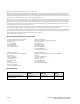
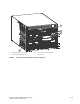
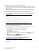
1 2 3 4 1 FC16-48 port blade (example, 4x) 3 Control processor blade (CP8) (2x) 2 Core switch blade (CR16-4) (2x) 4 Exhaust vent FIGURE 1 Port side of the Brocade DCX 8510-4 (sample configuration) Brocade DCX 8510-4 Backbone QuickStart Guide Publication Number: 53-1002178-01 5 of 24
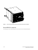
FIGURE 2 Port side of the Brocade DCX 8510-4 with the port side exhaust kit installed (sample configuration) Brocade DCX 8510-4, nonport side The following figure shows a sample configuration of the nonport side view of the Brocade DCX 8510-4.
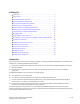
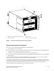
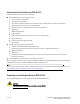
1 2 3 4 1 WWN card bezel (logo plate - WWN card behind) 2 Power supply (2x) 3 Blower assembly (2x) 4 Label with serial number and WWN FIGURE 3 Nonport side of the Brocade DCX 8510-4 (sample configuration) Time and items required for installation You can set up and install the Brocade DCX 8510-4 in the following ways: • As a standalone unit on a flat surface. • In a 19-in. Electronic Industries Association (EIA) cabinet, using a Brocade DCX 8510-4, DCX-4S Rack Mount Kit (either a 27-31 in.
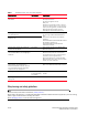
TABLE 1 Installation tasks, time, and items required Installation task Time estimate Items required Site preparation and unpacking Brocade DCX 8510-4 30 minutes 1/2-in. socket wrench (to remove pallet bolts). #2 Phillips screwdriver (for cable management comb). Pallet jack. Hydraulic lift or assisted lift, able to raise to a minimum of 140 cm (55 in.), with a minimum capacity of 113 kg (250 lb). The Brocade DCX 8510-4 weighs 68 kg (150 lb) with four FC16-48 port cards installed (192 ports).
The following steps are required to ensure correct installation and operation. 1. Provide a space that is 9 rack units (9U) high, 61.19 cm (24.09 in.) deep, and 43.74 cm (17.22 in.) wide. 1U is equal to 4.45 cm (1.75 in.). If you do not use the provided port side exhaust kit, the space needs to be only 8 rack units (8U) high. Plan to install the Brocade DCX 8510-4 with the nonport side facing the air-intake aisle.
Items included with the Brocade DCX 8510-4 The Brocade DCX 8510-4 ships with the following: • Brocade DCX 8510-4 chassis, populated with: - Control processor blades (CP8) - Core switch blades (CR16-4) - Port blades, application blades, and encryption blades (included based on customer specification) - Blade slot filler panels (for slots not filled by blades) - Port side exhaust kit (included based on customer specification) - WWN cards - WWN bezel (logo plate) - Power supplies - Power supply filler panel (
NOTE A fully populated Brocade DCX 8510-4 (four FC16-48 port cards, 192 ports) weighs approximately 68 kg (150 lbs) and requires a hydraulic or assisted lift to install it. 1. Unpack the Brocade DCX 8510-4. a. Cut the bands that encircle the packaging. b. Remove the lid and the kits and foam from the top of the chassis. c. Lift the cardboard box off the chassis and remove the plastic bag from around the chassis. Save the packing materials for use when returning the old chassis. d.
1. Connect the two AC power cords to the two power supplies. 2. Connect the power cords to a power source with voltage of 200 to 240 VAC, 47 to 63 Hz or optionally to a power source with voltage of 110 to 120 VAC, 47 to 63 Hz. If using any application blades in the chassis, the 200 to 240 VAC option is necessary in order to achieve power supply redundancy. ATTENTION Use of the high-voltage line (200 to 240 VAC) is highly recommended because of better power-conversion efficiency.
ATTENTION Do not route the cables in front of the air exhaust vent, which is located at the top of the port side of the chassis.If you are using the Port Side Exhaust Kit with your Brocade DCX 8510-4, there is also an exhaust vent at the bottom of the port side of the chassis. Use the vertical cable fingers to keep the cables away from this exhaust vent as well.
Please note that the duplex clip on the mSFP end of the cable is black for easier recognition. See the appendix for a listing of the qualified mSFP optical cables for the FC8-64 port blade. If ISL Trunking is in use, group the cables by trunking group. The ports are color-coded to indicate which ports can be used in the same ISL Trunking group: eight ports marked with solid black ovals alternate with eight ports marked with oval outlines.
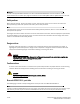
The figure below shows an QSFP cable and transceiver. The QSFP connectors on the core blades are labeled by trunk group (trunking is optional) for ease of installation. The subsequent figures shows acceptable cabling configurations for the ICL feature. The recommended topology is the parallel type where there are four QSFP cables connected between any pair of Brocade 8510 series chassis.The full mesh configuration is also supported.
1 1 Chassis 1 FIGURE 7 2 2 Chassis 2 QSFP cable connections – 8510 sample configuration - parallel type Establishing a serial connection and logging on to Brocade DCX 8510-4 To establish a serial connection to the console port on the Brocade DCX 8510-4, complete the following steps. 1. Verify that the Brocade DCX 8510-4 is powered on and that POST is complete by verifying that all power LED indicators on the port, control processor, and core switch blades display a steady green light. 2.
ATTENTION The CONSOLE port is intended primarily for the initial setting of the IP address and for service purposes. 3. Access the Brocade DCX 8510-4 using a terminal emulator application (such as HyperTerminal in a Windows environment or tip in a UNIX environment). 4. Disable any serial communication programs running on the workstation (such as synchronization programs). 5.
2. (Optional) Modify passwords. To skip modifying the password, press Ctrl-C. For more information on passwords, refer to the Fabric OS Administrator’s Guide. NOTE Passwords can be 8 to 40 characters long. They must begin with an alphabetic character. They can include numeric characters, the dot (.), and the underscore (_) only. Passwords are case-sensitive, and they are not displayed when you enter them on the command line. For more information on passwords, refer to the Fabric OS Administrator’s Guide.
Ethernet Subnetmask [0.0.0.0]: 123.123.123.123 Fibre Channel IP Address [0.0.0.0]: Fibre Channel Subnetmask [0.0.0.0]: Issuing gratuitous ARP...Done. Committing configuration...Done. swDir:admin> ipaddrset -cp 0 Host Name [cp0]: Ethernet IP Address [10.77.77.75]: 123.123.123.121 Ethernet Subnetmask [0.0.0.0]: 123.123.123.123 Gateway IP Address [0.0.0.0]: 123.123.123.124 IP address is being changed...Done. Committing configuration...Done. swDir:admin> ipaddrset -cp 1 Host Name [cp1]: Ethernet IP Address [10.
NOTE Changing the name causes a domain address format RSCN to be issued. 1. Type switchName followed by the new name in double quotes. swDir:admin> switchName "swModularSwitch5" Committing configuration... Done. swModularSwitch5:admin> 2. Record the new name for reference. Customizing a chassis name The chassis name of the Brocade DCX 8510-4 can be up to 15 characters long; can include letters, numbers, hyphens, and underscore characters; and must begin with a letter. 1.
Verifying PID mode Before connecting the Brocade DCX 8510-4 to the fabric, verify that the port identifier (PID) mode on the Brocade DCX 8510-4 matches the other switches in the fabric. This parameter must be identical for all switches in the fabric and is set using the configure command. Installing transceivers Follow these steps to install SFP+s and mSFPs (FC8-64 port card only) and cables to the Brocade DCX 8510-4.
1. Position one of the QSFP transceivers so that the key is oriented correctly to the port. Insert the transceiver into the port until it is firmly seated. Transceivers are keyed so that they can only be inserted with the correct orientation. If a transceiver does not slide in easily, ensure that it is correctly oriented. When the transceiver is correctly seated, the status LED will flash amber several times and then turn solid amber. 2.
736 3 16 4 ------737 3 17 4 ------738 3 18 4 ------739 3 19 4 ------740 3 20 5 ------741 3 21 5 ------742 3 22 5 ------743 3 23 5 ------744 3 24 6 ------745 3 25 6 ------746 3 26 6 ------747 3 27 6 ------748 3 28 7 -----id trunkmaster name (Trunk master) 749 3 29 7 -----id trunkmaster name (Trunk master) 750 3 30 7 -----id trunkmaster name (Trunk master) 751 3 31 7 -----id trunkmaster name (Trunk master) 16G 16G 16G 16G 16G 16G 16G 16G 16G 16G 16G 16G 16G No_Module No_Module No_Module No_Module No_Module
4. Verify the correct operation of the Brocade DCX 8510-4 in the fabric by entering the fabricShow command from the workstation. This command provides general information about the fabric. 5. To back up the configuration, run the following two steps: a. Enter the configupload -vf command. This command uploads the Brocade DCX 8510-4 virtual fabric data. b. Enter the configupload command. This command uploads the Brocade DCX 8510-4 configuration. 6.