
Owner manual


Brocade 7800 Extension Switch Hardware Reference Manual 5
53-1001350-04
Introducing the Brocade 7800 Extension Switch
1
Nonport side of the Brocade 7800
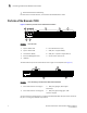
Figure 3 shows the nonport side of the Brocade 7800 Extension Switch, which contain the
combined power supplies and fans.
FIGURE 3 Nonport side of the Brocade 7800 Extension Switch
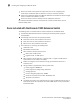
Brocade 7800 management
You can use the management functions built into the Brocade 7800 to monitor the fabric
topology, port status, physical status, and other information to help you analyze switch
performance and to accelerate system debugging.
NOTE
The Brocade 7800 automatically perform a power-on self-test (POST) each time it is turned on.
Any errors are recorded in the error log. For more information about POST, see “POST and boot
specifications” on page 35.
For information about upgrading the version of Fabric OS installed on your Brocade 7800, see
the Fabric OS Administrator’s Guide.
1 Fan and Power Supply Assembly 2 7 Fan assembly 1
2 Fan and Power Supply Assembly 1 8 FRU LED
3 Fan assembly 2 9 Power supply 1
4 FRU LED 10 Fan assembly 1
5 Power supply 2 11 FRU handle
6 Fan assembly 2 12 FRU handle
111 12
3 4
8
5 6
7
9
2
10